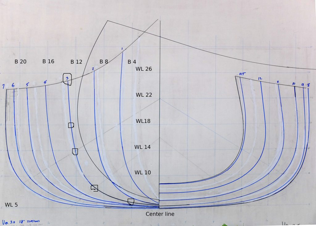
Lofting has two main objectives. The drawings represent the shape of the boat full size and so can be used to make templates for parts. Secondly, the drawings allow the builder to confirm that the shape of the boat will be fair, that is, without lumps and bumps. There are three views of the boat produced when lofting : the body plan, which is the boat viewed from directly ahead or astern; the profile plan, which is the boat seen from the side; and the half-breadth plan, which is the boat viewed from overhead. The image above is an example of a body plan. The curved lines show the shape of the hull at specific ‘stations’ spaced at regular intervals along the length of the boat. Commonly, the stations forwards of the middle of the boat are on one side and the aft stations are on the other side in the drawing. One of the main uses of a body plan is to make the forms that the boat is built on.
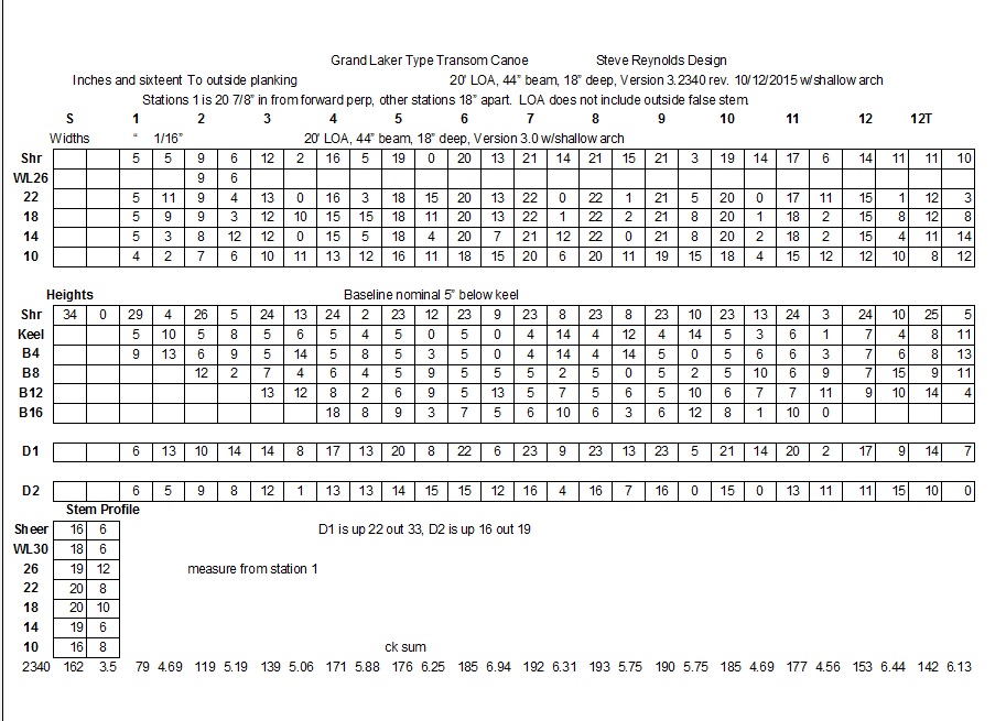
A table of offsets is the key to building a boat. It gives measurements to points which, when connected in a smooth curve, represent the shape of the boat at all the stations and in all three views. The table of offsets above is for my grand laker canoe design, which also is shown in the body plan above. There are 12 stations plus measurements for the S(tem) and vertical projection of the T(ransom). Station 1 is 20-7/8″ back from the forward face of the stem, all others are spaced 18″ apart. The measurements are in inches and sixteenths of an inch.
The first set of numbers titled ‘Widths’ shows measurements to points horizontally out from a centerline at different ‘waterlines’. Waterlines are horizontal slices through the hull at different heights above a baseline. The choice of waterlines is arbitrary but can make things easier or harder depending. In my design, I elected to establish a baseline about 5″ below and parallel to the mid-section of the intended keel, and draw waterlines parallel to the baseline starting 10″ above the baseline and then every 4″.
The second set of numbers titled ‘Heights’ shows measurements vertically up from the baseline at different ‘buttocks’. Buttocks are vertical slices through the hull parallel to the centerline at different distances out from the centerline. Again, the choice of buttocks is arbitrary, and I chose to draw buttocks every 4″.
The Diagonals D1 and D2 are a third set of measurements to check the fairness of the hull. Their placement is selected in an attempt to have the diagonal lines cross the station lines at close to right angles, and they are defined as being ‘X’ inches up from the baseline and ‘Y’ inches out from the centerline. The measurements are from the end of the diagonal on the centerline to the point at the desired station.
To begin a body plan drawing, a suitable surface is prepared – 1/4″ plywood with a coat of flat white primer is good – and for my boat, a piece about 42″ tall by 48″ wide is sufficient to draw the stations full size. The centerline, waterlines and buttock lines are drawn in and labeled and then you can begin marking the points for each station from the Widths, Heights and Diagonals. In the example below, looking at Station 3, we see that at waterline 18, the measurement from the centerline out is 12-10/16″ or, 12-5/8″. Station 3 height at buttock 4 is 5-14/16″, or 5-7/8″. Likewise, the measurement for diagonal 1 is 14-1/2″ and diagonal 2 is 12-1/16″.
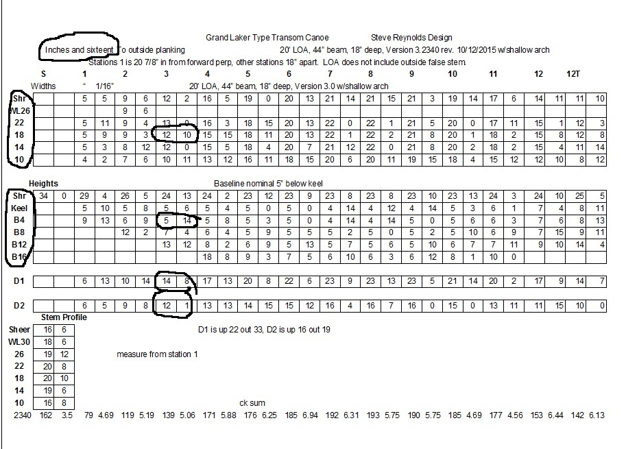
Transferring these to the body plan, we get the points circled below. After all the points for a station are drawn, the points must be connected in a smooth curve, and this is done with flexible battens of various material – I use wooden ones in different sizes and you have to get creative about holding things in place while you draw the lines.
When you have finished drawing all the stations you have something – even if just a nice drawing to put on the wall. I will discuss the profile and half-breadth views in another blog.