Putting an electric outboard on my motor canoe is appealing for a few reasons. First, compared to a gas outboard, the electrics are quieter, and the ones with lithium batteries are lighter. They are more easily carried in that you don’t have to worry about spilled gas in the car and there are none of the cautions necessary with transporting 4-strokes in how you place them to prevent crankcase oil from flooding the engine. They can run at slower speeds for trolling. I tried a Minnkota motor on my Grumman canoe but sold it because of the battery weight – it was as heavy as my 6-hp Yamaha 4-stroke. I took a leap and bought a Torqeedo.
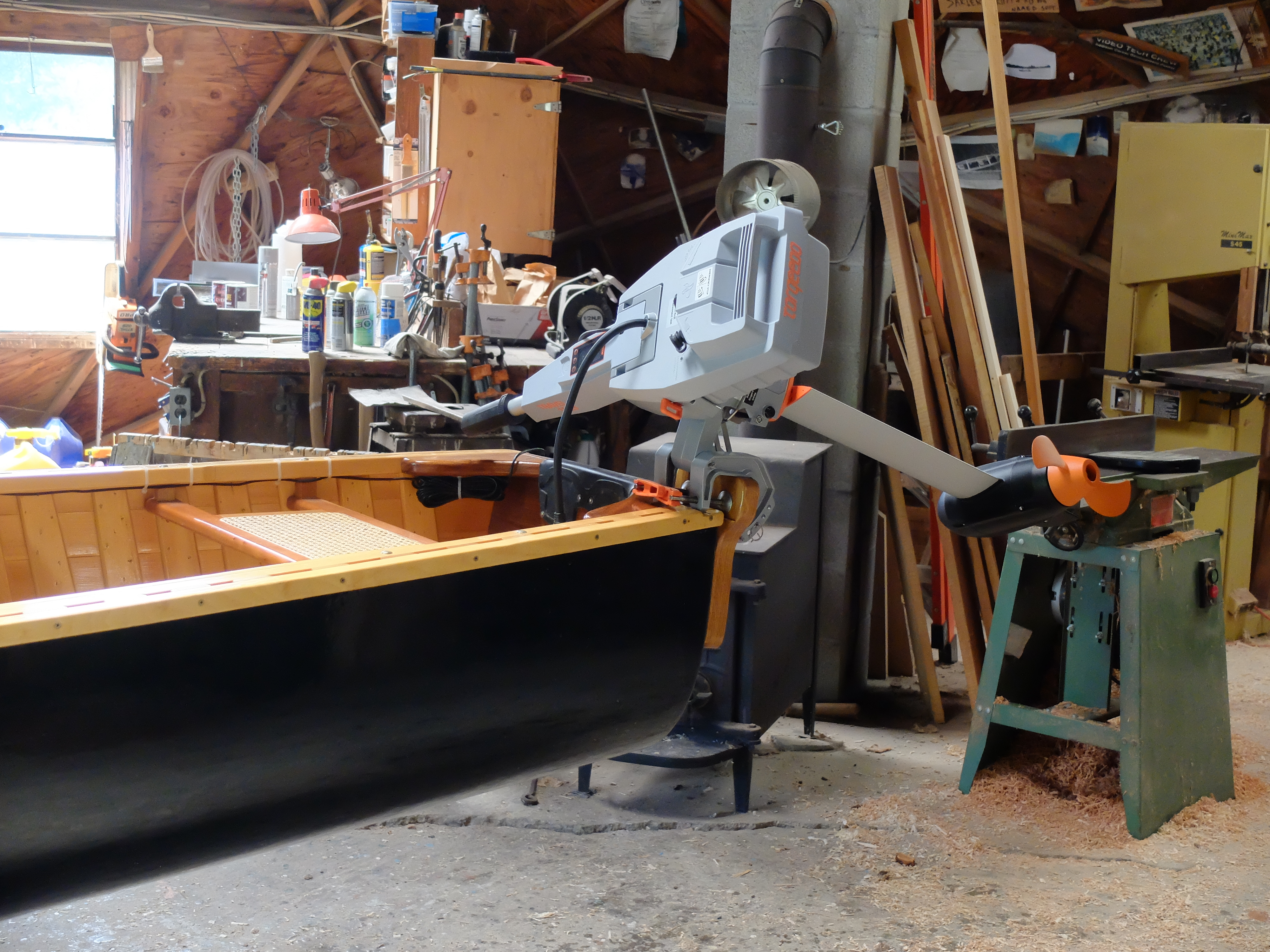
It has a lithium battery. It separates into 3 pieces for transport. It has a nominal 3-hp. It took some doing to get it installed on my canoe.
First, the tiller of the Torqeedo is centered on the motor, unlike a gas outboard with the tiller on the side. With the gas motor, you can center the motor and sit more or less on center and comfortably hold the tiller, which you cannot do with the electric. This setup ruled out putting the Torqeedo in the same position on the transom as the gas motor, so some kind of mount to one side was needed. The second peculiarity of the Torqeedo tiller is that is doesn’t functionally tilt up, like a gas motor. In use, it has to remain straight out, because if you tilt it up is comes out of its mounting bracket. It is designed this way to make the motor easy to disassemble for transport, but inconvenient for tilting – so, besides putting the motor to the side, you also have to be sure it can tilt since raising the motor when beaching or avoiding rocks is the order of the day with a motor canoe. Because of the battery weight on the back of the motor, it will naturally twist to one side as you tilt it, but you have to take some care in making this maneuver.
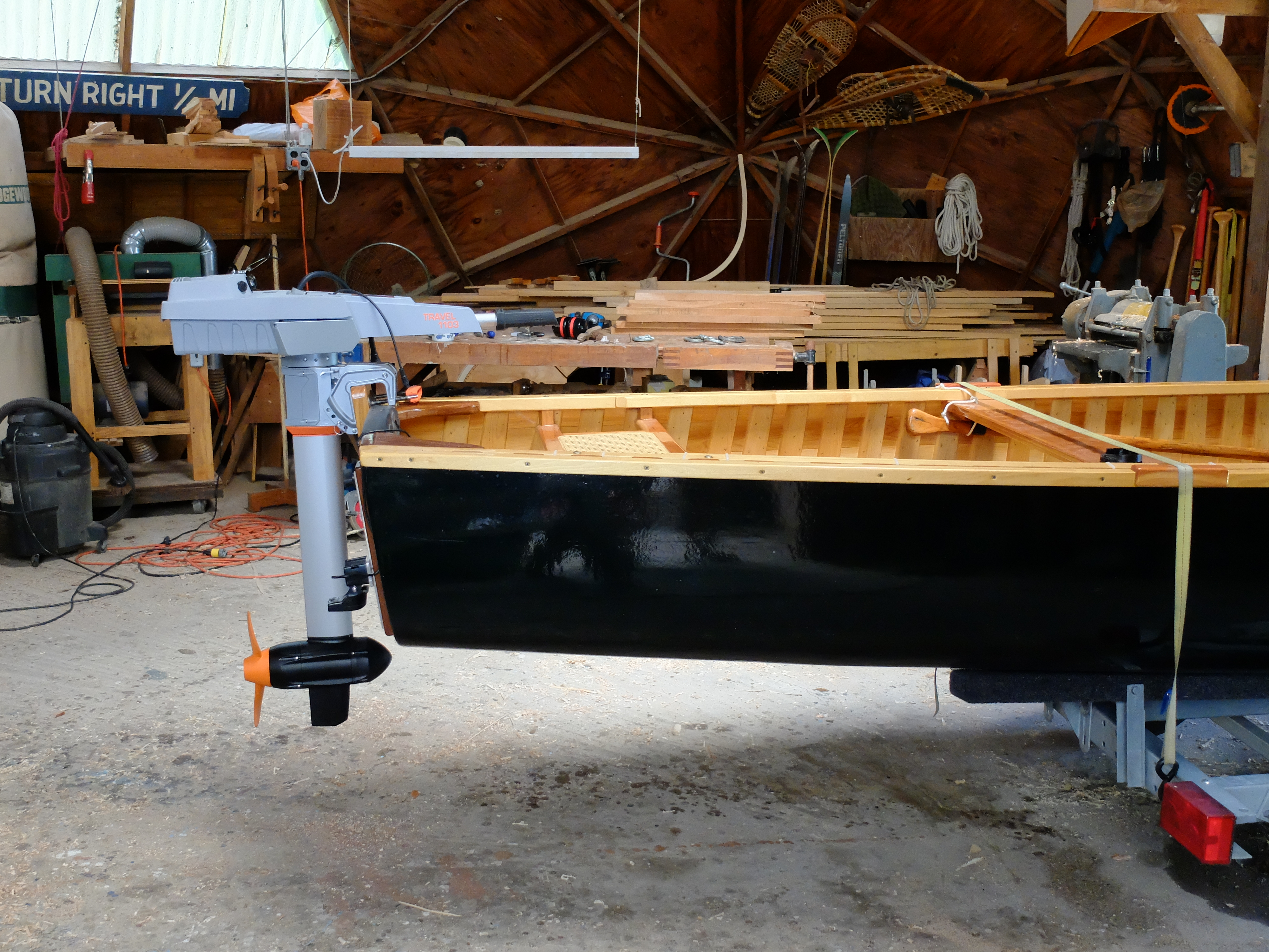
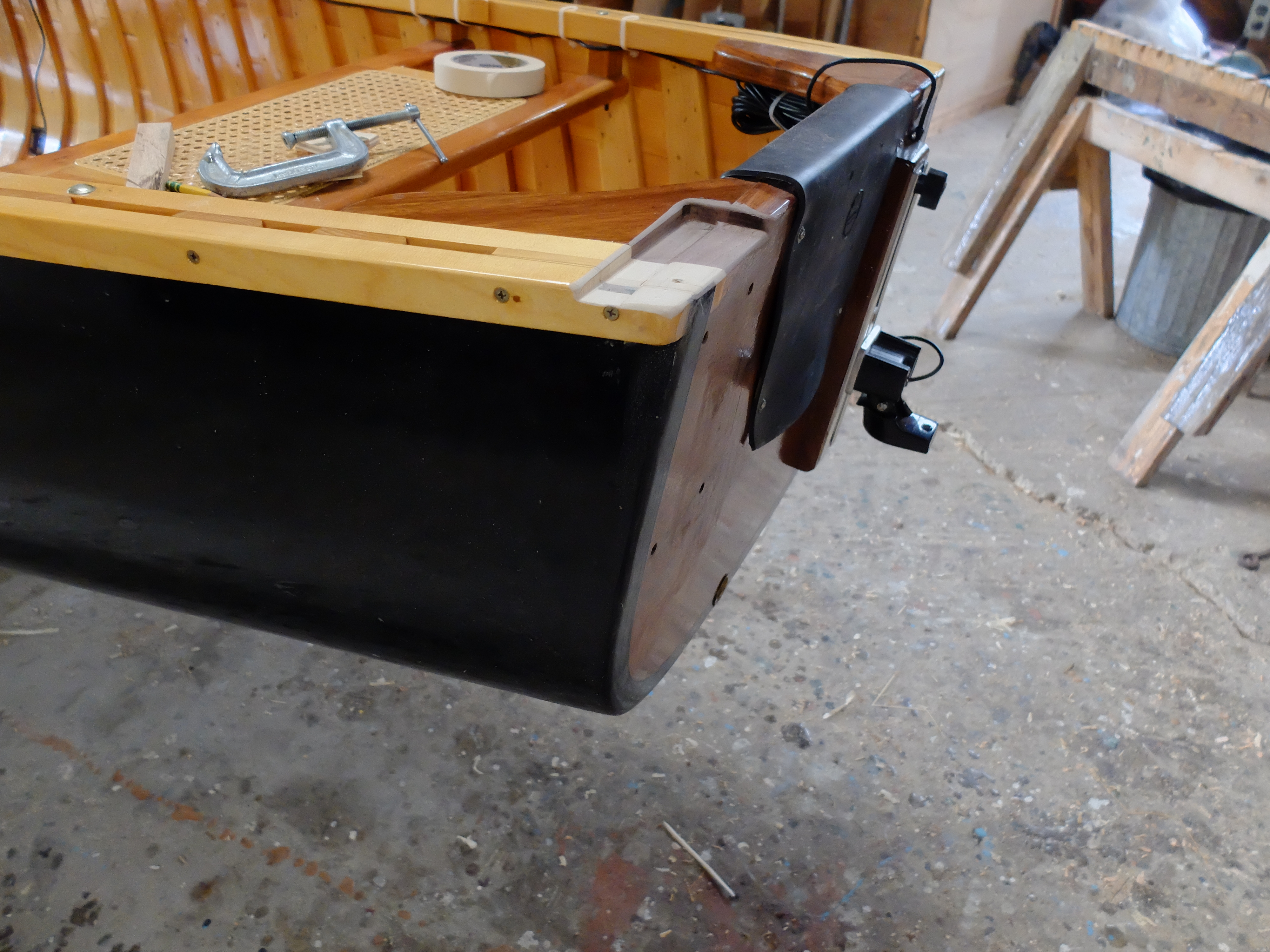
The second problem is getting the prop deep enough to avoid cavitation. News to me, Torqeedo’s 2 shaft lengths – ‘short’ and ‘long’ – are not exactly comparable to what we are used to in the gas motor world as short and long. The Torqeedo short is a good 2-1/2″ longer from top of transom to centerline of prop than the Yamaha. It was not immediately apparent why this was, so I made my first bracket for the Torqeedo to match the prop centerline height of the Yamaha. I made a white oak mount through-bolted to the port side of the transom, 2-1/2″ taller than the transom, so the centerline of the Torqeedo prop was as the same height as the Yamaha –
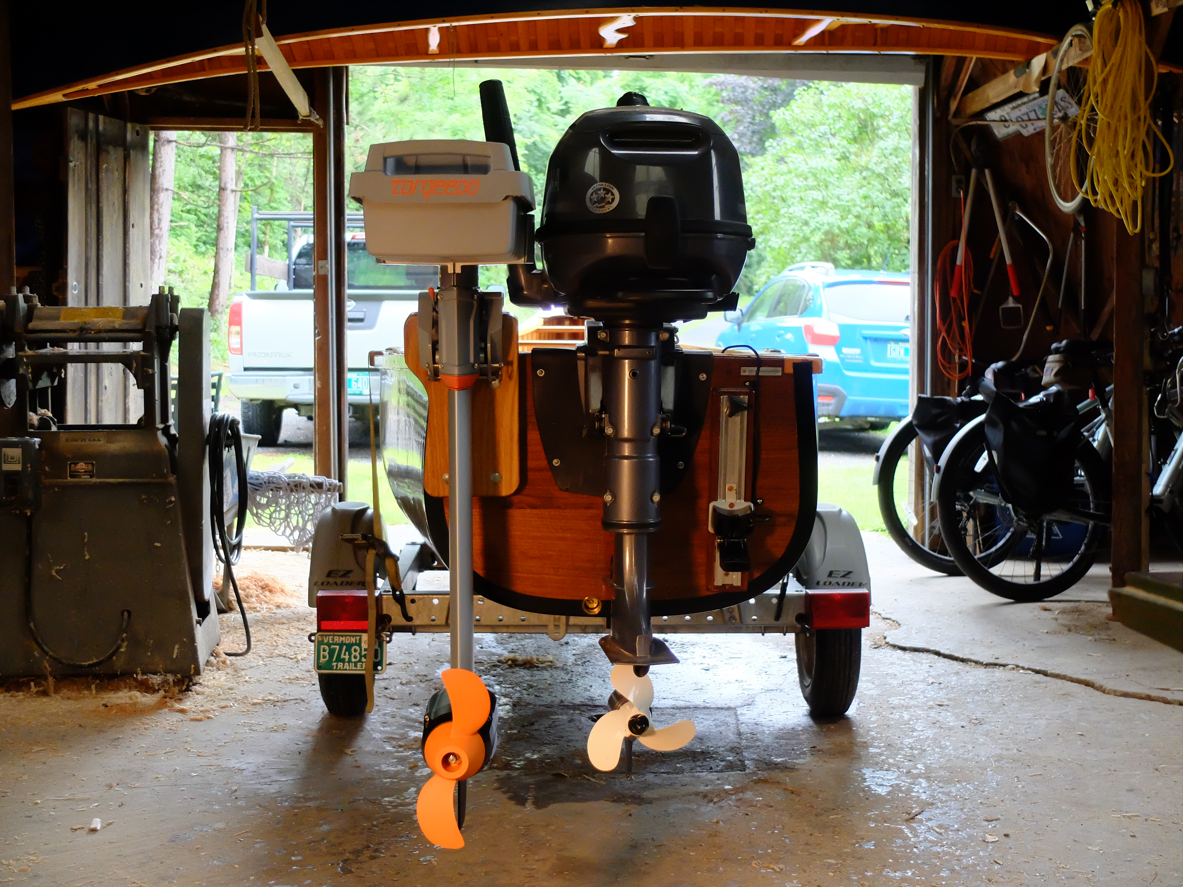
I made sure the top of my add-on mount would not interfere with the tiller of the Yamaha. Two obvious differences are the prop sizes – the Yamaha is 7-1/4″ diameter while the Torqeedo is 10-1/4″, and the shaft length previously noted. Also, the underwater bulk of the Yamaha is significantly smaller than the Torqeedo, which includes the full motor, and further, the Yamaha has an anti-cavitation plate which the Torqeedo does not. When I took it out for a test drive I found that the prop cavitated at any speed above 5 MPH, and that was only using about one-third throttle. There seemed to be lots more power to the motor which wasn’t being put to use and certainly nothing equivalent to the Yamaha which was happy at full throttle and 14 MPH. On the plus side, it slid along at 2-3 MPH almost silently and would do that for probably 8 hours on a single charge, and could be fine adjusted to optimal trolling speed without the noise, vibration, trolling bucket etc. rig I use with the gas engine.
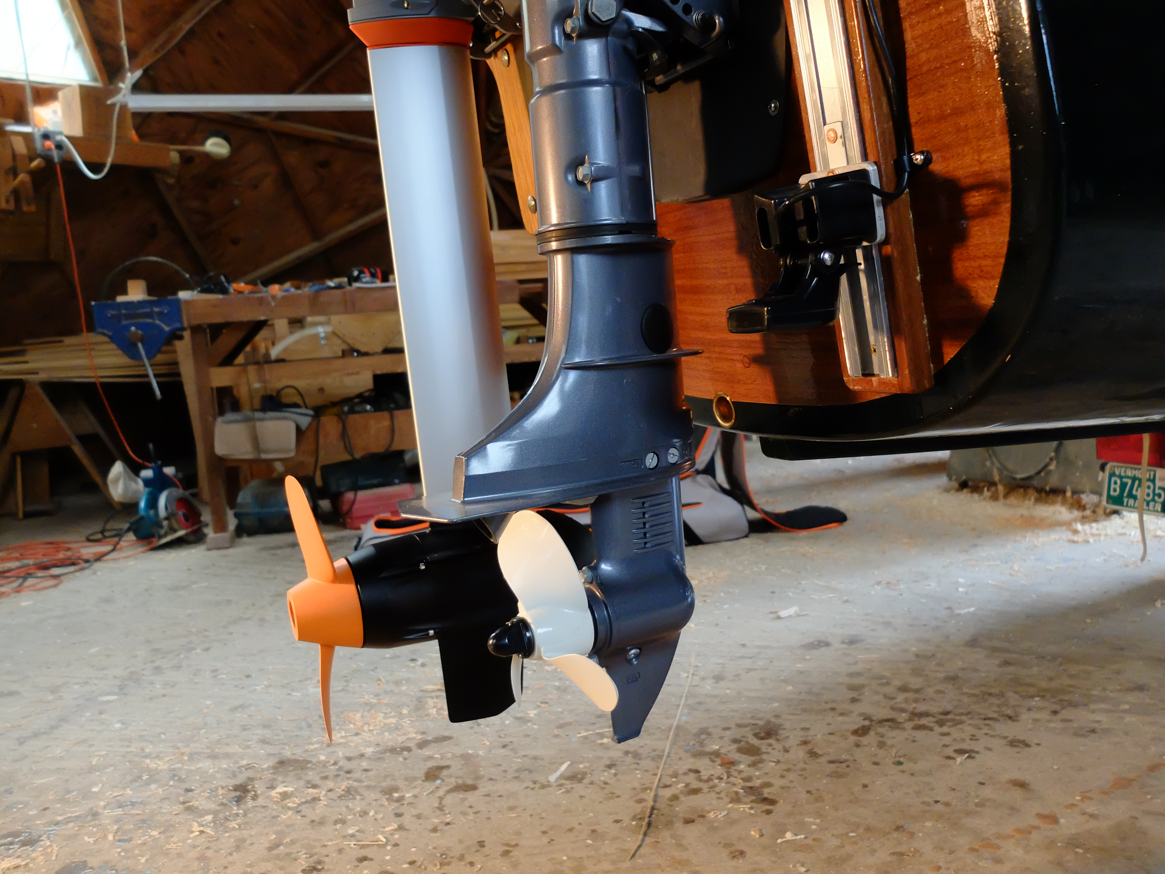
‘Research’ revealed that electric motors turn at slower speeds than gas, and need larger props to be efficient, and I hadn’t provided the minimum requirement of 1-1/2″ of water between the top of the prop and the bottom of the hull at the transom (this is not stated in the Torqeedo manual). I only had 3/4″. Ah-ha! That is why the shafts are longer on electrics. I had to lower my mount. There was only so much I could do while still retaining my transom corner braces, but I was able to lower the mount by 3/4″ by cutting out a recess for the motor brackets.
The motor can still tilt, albeit carefully, and I have 1-1/2″ between top of prop and bottom of hull, so things should be better. I will try it as soon as it stops raining.
I had the boat out for a few days fishing. The Torqeedo performed perfectly, using only 30% of its battery over 8 hours of speeds around 2 MPH. It still won’t push the boat above hull speed, and battery use increases significantly as speed goes up, but that is not what I want it for. I don’t hesitate taking it out for a whole day with just the Torqeedo, knowing what I can get out of a single charge. One thing I did find out is that the plastic pin securing the battery will sink if dropped overboard – nice that it is bright orange.