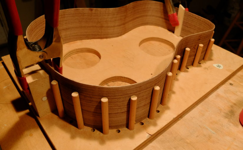
Two new guitars in process – a steel string dreadnought with curly black walnut body and mahogany neck, and a 17″ archtop. The blog entry about making a fingerboard shows the neck for the dreadnought. Pictures below – dreadnought back glued up, braced and ready for top to be glued on. This guitar uses a mortise/tenon bolt-on neck. I’ve switched to solid linings because I hate cutting kerfed lining. Solid is quicker and can be a little narrower. These linings are made of Spanish cedar pre-bent on the bending iron. Nice curl to the walnut.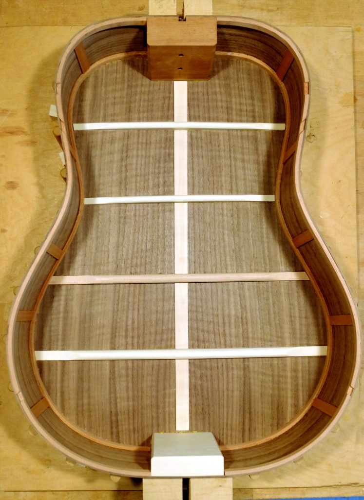 The top braced and ready to glue – nicely quarted, fine grained Sitka spruce.
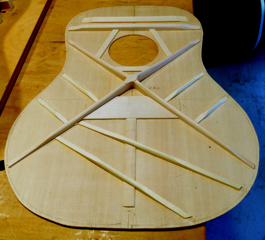 Gluing up the top – the rubber bands keep the spool clamps from slipping off the edge.
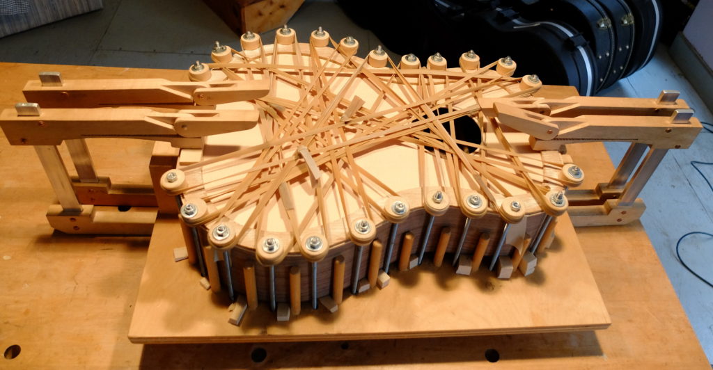 First finish coats – de-waxed shellac sealer with oil varnish top coats. I used curly hard maple for the binding which contrasts nicely with the walnut.
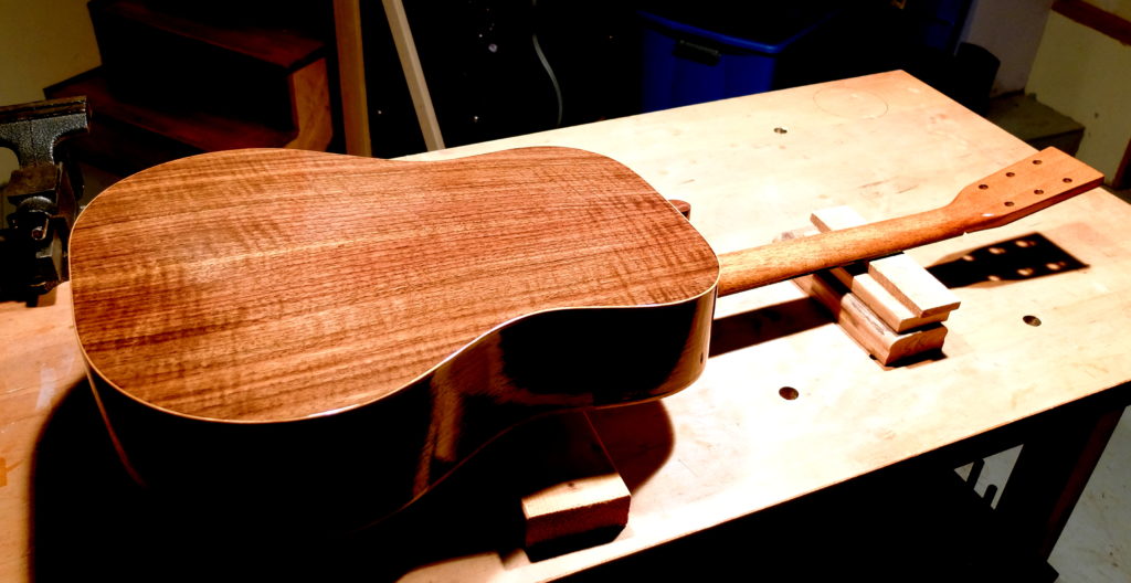 This is the archtop – sides bent, solid lining in (these are black cherry), neck and tail blocks in.
 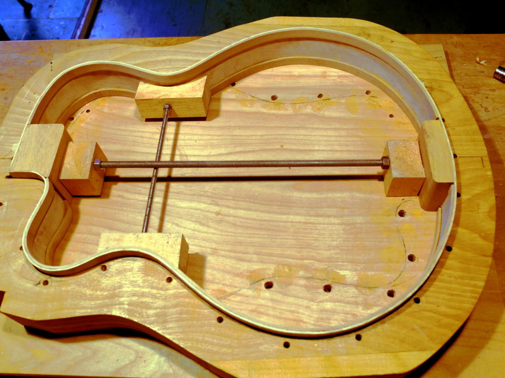 The back mid-carving – this is quilted big leaf maple with a curly hard maple center. Very slow going on the carving because of the hardness and interlocked grain of the maple – over 8 hours. After putting the outside profile on using templates, the inside is drilled on the drill press to a uniform depth and worked down to a thickness of 3/16″.
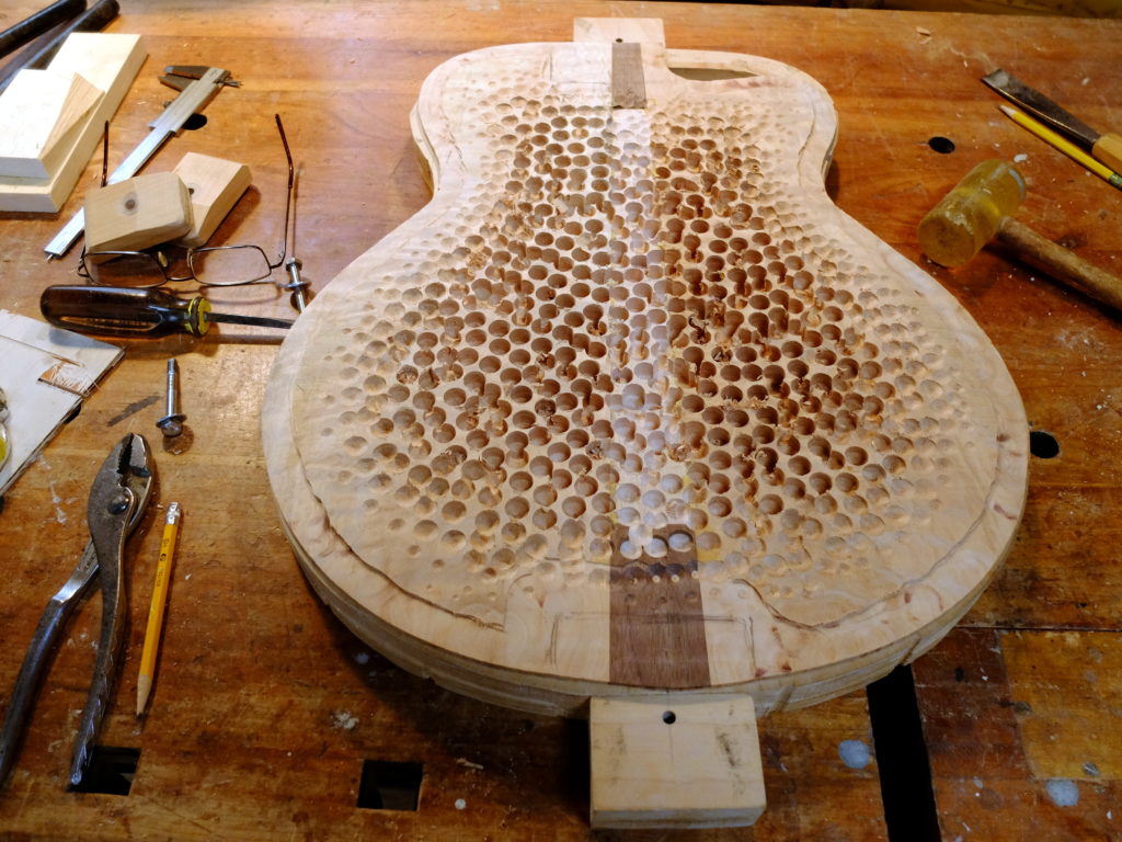 The back ready to be glued on.
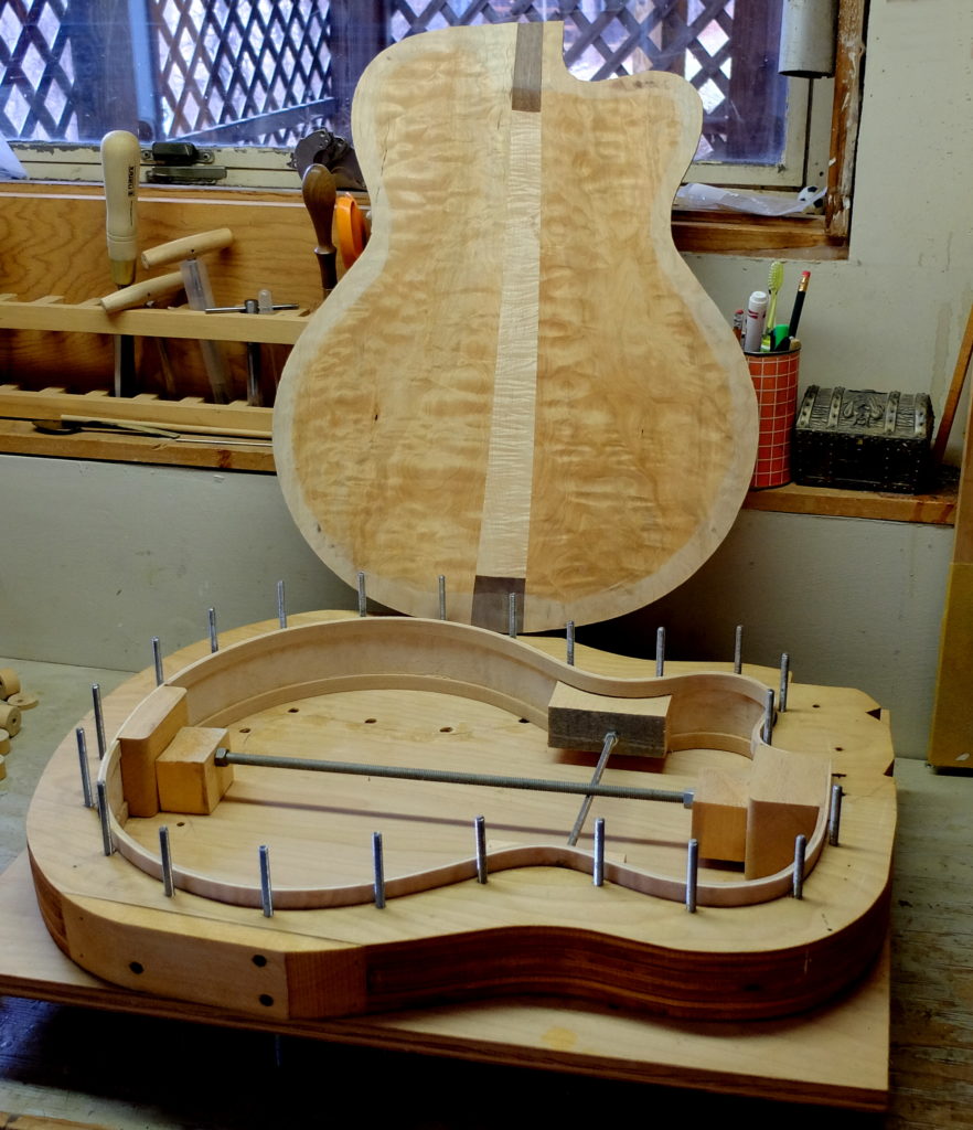 Glued on but not trimmed yet. It’s going to be very pretty.
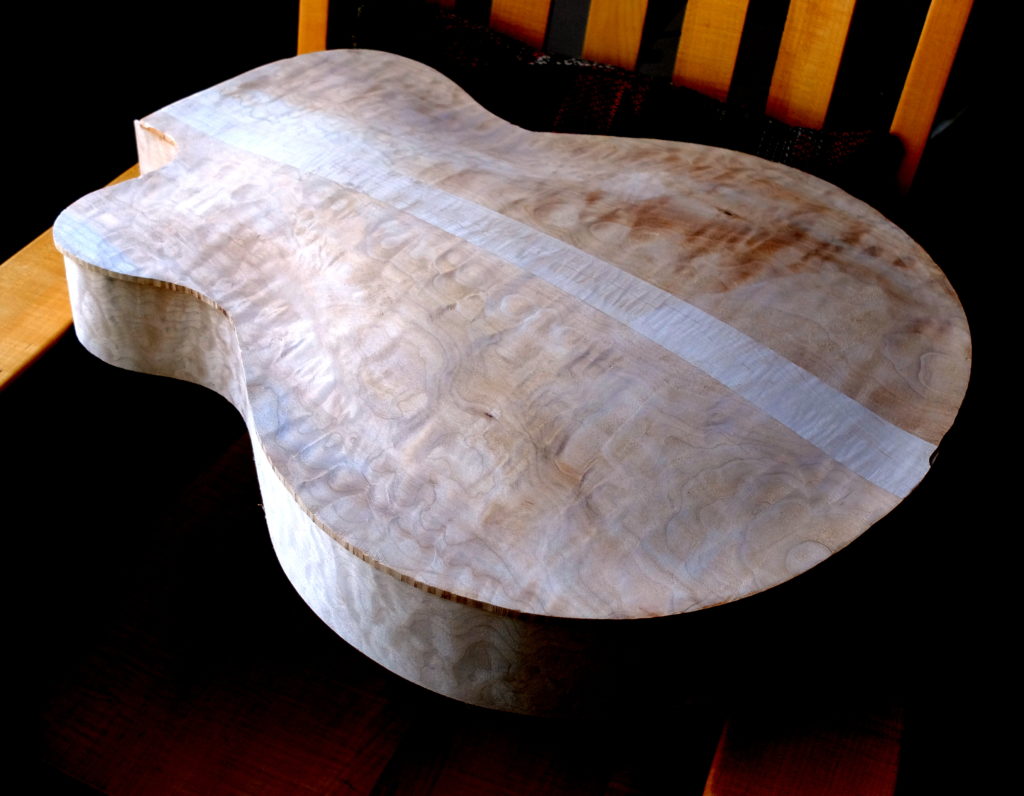 The top mid-stream in carving which is where I left it to get a hip replacement. I’ll be able to resume work on it in a couple weeks.
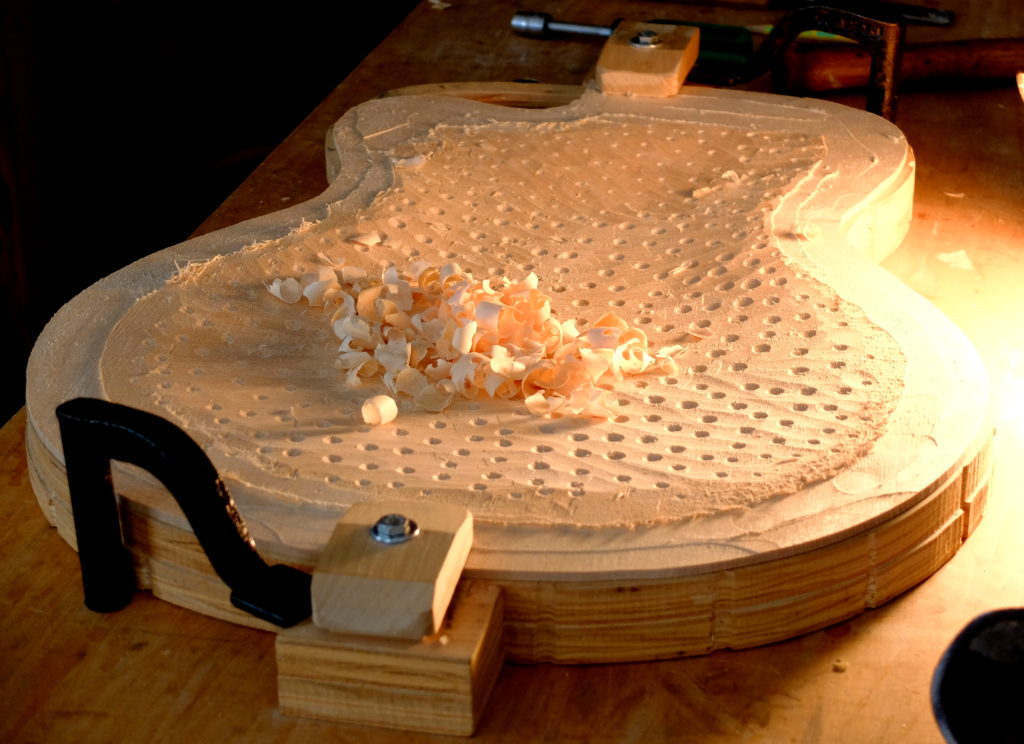
Month: April 2017
Moisture Management in Cabin Structures
My previous blog was about a system for a cabin deck structure. Observant readers may have noted the absence of any additional vapor barrier. This was intentional – and deserves an explanation.
In my part of the country (New England) it used to be standard procedure to incorporate a plastic polyethylene vapor barrier directly behind all interior surfaces, be they walls, floors or ceilings. This was to prevent moisture moving from an insulated and therefore warmer space (interior) towards the outside colder space and encountering the dew point along the way in the middle of the wall/floor/ceiling and condensing inside that structure. When condensation occurs inside the building structure all kinds of problems can result, ranging from such things as peeling exterior paint to rot and mold inside and throughout the wall. With the present emphasis on energy efficiency in buildings, the problem of moisture control has become more complex, and the old standards, like always using a vapor barrier, are no longer taken for granted. Builders may be constrained by building codes which dictate required structural components, insulation, etc., all primarily intended for year-round residences but overkill and inappropriate in some ways for seasonal cabins. For example, the design criteria for energy efficiency presents as the ideal a very tight building with all interior air ‘conditioned’ year-round. If you can build to your own design it will pay to understand moisture management, as the best system for a cabin may actually be less tight and more open.
There is a wealth of published material on this topic, one source being Joseph Lstiburek of Building Science Inc. The Journal of Light Construction published a practical and thorough book called The JLC Guide to Moisture Control. Reading these can produce some confusion until certain basic elements are grasped. The problem is partially that terms have changed – the addition of the new concept of an ‘air barrier’ as distinct from a ‘vapor barrier’ being an example. The problem is also partly because moisture movement depends on temperature differences between spaces – so one set of procedures applies to Northern climates, whereas a a different structural procedure may apply in Southern climates, all based on the same principles. So – what are the principles?
The first is that moisture moves from warm spaces towards cooler spaces. If, along the way, moisture encounters the dew point inside a structure, it will condense. The second is that you must always provide a path for moisture to move out of a structure once it gets in. This means ‘no double-sided vapor barriers’. You have to decide which surface – interior or exterior – you want to be the drying surface. Thirdly, most moisture moves in the air, with very little by comparison by direct diffusion. This is where the concept of the air barrier is useful.
One can easily find examples of building systems used in the past that created their own fiasco. The use of Tyvek house wrap with red cedar clapboards applied directly on top (no air space) is one. The tannins in the cedar degraded the water resistance of the Tyvek, turning it into a sponge that absorbed moisture, especially on warm days in the sun following a rain – driving the moisture into the sheathing and eventually bringing rot to the entire wall. There remains value in my mind in tried-and-true methods that a cabin builder can use, and avoid some of the experimentation with new systems and products which may turn out to be their own problems after a few years. For example, some of the products now in use, like the ZIP system of plywood sheathing with a pre-applied waterproof surface, call for special attention to the ‘no-double-sided vapor barrier’ rule. I think, done wrong, these will lead to problems. Understanding the principles will help do them right.
Going back to my floor structure. The main moisture drive will be from inside the building to the outside. There are small air spaces between the foam insulation and the subfloor, but most air infiltration into that space will be outside air because the subfloor is glued tongue-and-groove acting as a pretty good air barrier. During construction the subfloor will get wet and some moisture will make it through the subfloor to the insulation. The main object then is to allow a way for the floor to dry out. It will dry to the inside. Any moisture that gets into the air space from outside will only condense if the floor structure is cooler than the outside air, which is not likely unless the cabin is heavily air conditioned, which is not in the plans for this building. The poly vapor barrier would only get in the way and was therefore omitted.
Cabin Flooring System
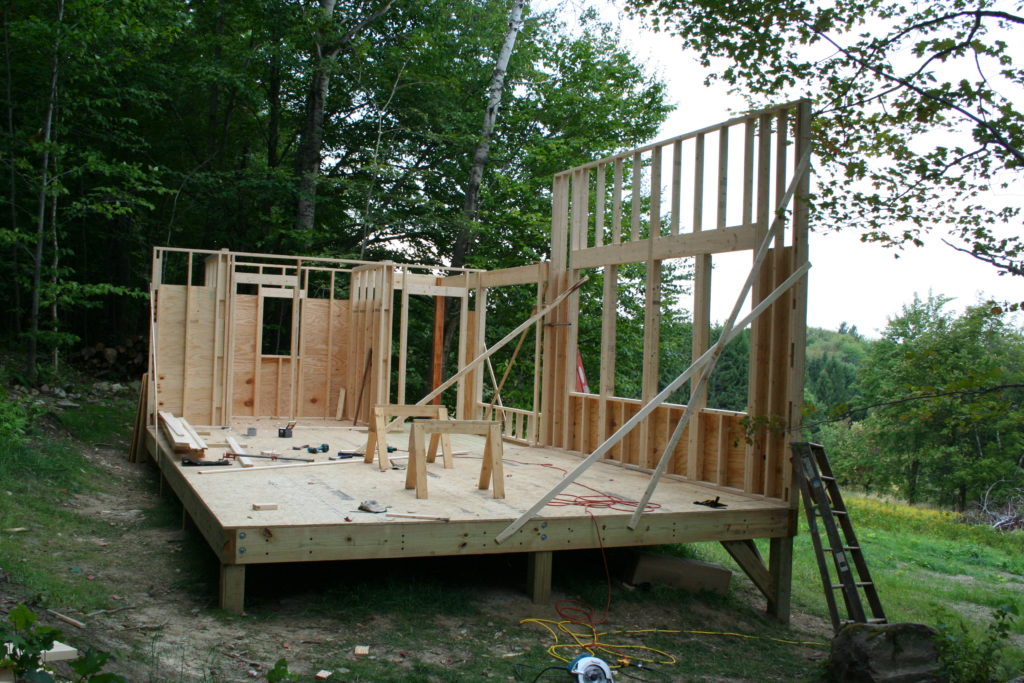
I have built a small number of seasonal cabins and now use a flooring system that has some advantages over other methods. By ‘floor’ I am referring to the main deck of the cabin which is built on posts without any basement type foundation. My cabins have been built in places where all materials are carried in to the site by people, meaning the sites are not accessible by cement truck, and neither is it desirable to use excavating equipment because of the clearing that would be needed to get an excavator to the site and give it room to work. So, first of all, this method allows all work to be done by hand and allows the use of materials which can all be carried in by hand. The use of a post foundation means that the deck is above but usually close to ground level. While the underside of the deck / joists could be left open, in most cases it is desirable to use some insulation and that then means that the insulation must be sealed from below to prevent mice and other rodents from getting into the assembly and thence into the cabin. It is assumed that the cabin will be unoccupied for long periods of time, like most of the winter, and the last thing you want is rodents getting in and making a mess. It is also worth thinking about the space under the deck and how to keep larger animals like opossums from making themselves to home – the best solution being to be to keep the sides of the deck clear, omit any kind of skirting, and checking every now and again for signs of anything trying to den up down there.
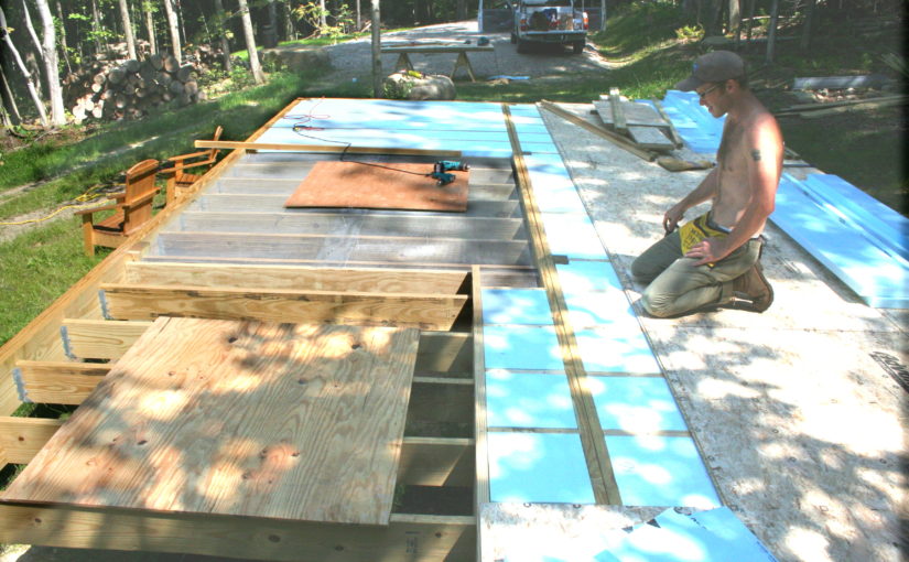
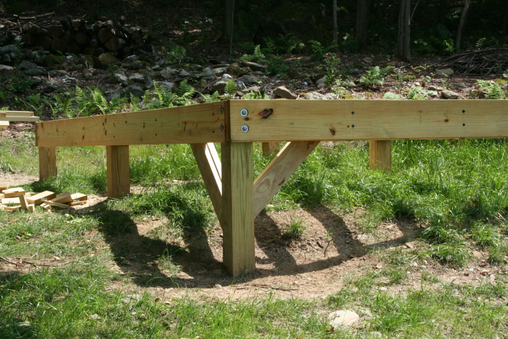
The foundation consists of posts which can be wooden PT set on a concrete pad below whatever you consider frost level, or you can use concrete posts poured in sona tube. In this case, a cabin my son Luke and I built in Vermont, we used 6×6 PT posts set 4′ deep, each one resting on a bag of sacrete. The peripheral beams are double 2×10 PT let into the posts and lagged to eachother. Posts are every 8 feet. The main deck is 16′ x 24′, and there is a central carrier beam so we could use 8′ joists. Below – posts in and peripheral beams ready for joists.
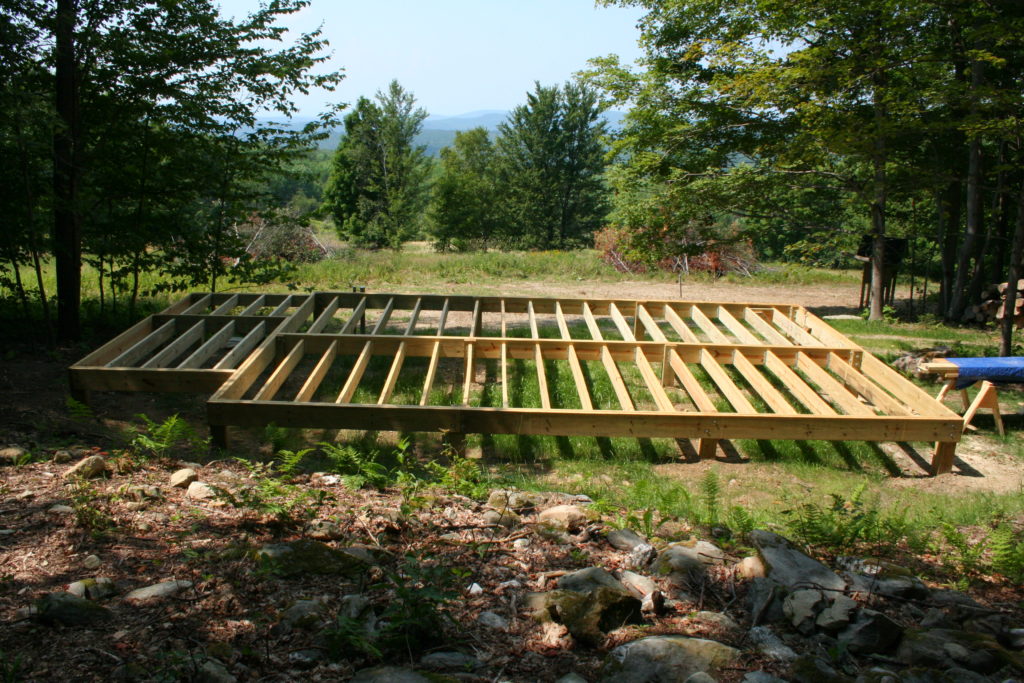
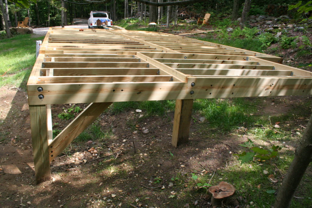
The 2×8 joists are set in joist hangers 2″ below the top of the peripheral beam to leave room for foam insulation.
A layer of 1/4″ mesh hardware cloth is carefully laid directly on top of the joints – this is the rodent block, and then 2″ blue-board foam insulation is fitted into all the spaces between joists. Sleepers 2″ tall are nailed to the top of the joists, bringing everything up to the level of the peripheral beams, and then the Advantech subfloor goes on. Pressure treated lumber is used for all structures below the subfloor.
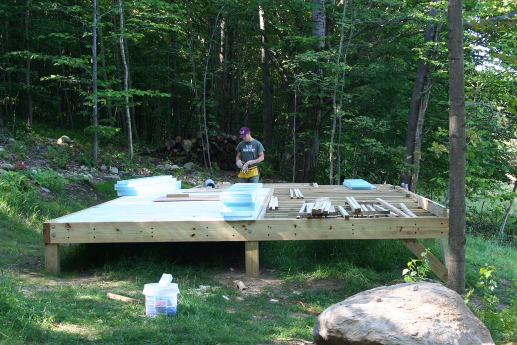
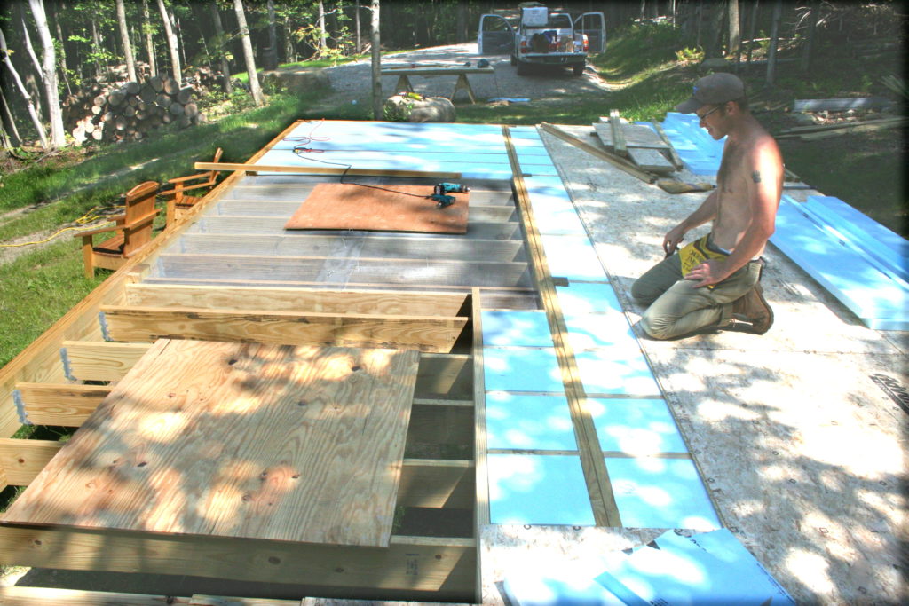
And then you can start framing.