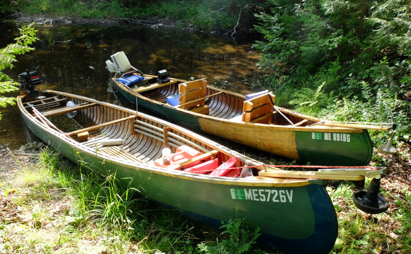
I got my first up-close look at these canoes in western Maine this summer, and have started a project to build one for myself. In this blog I intend to document the process for those who are interested.
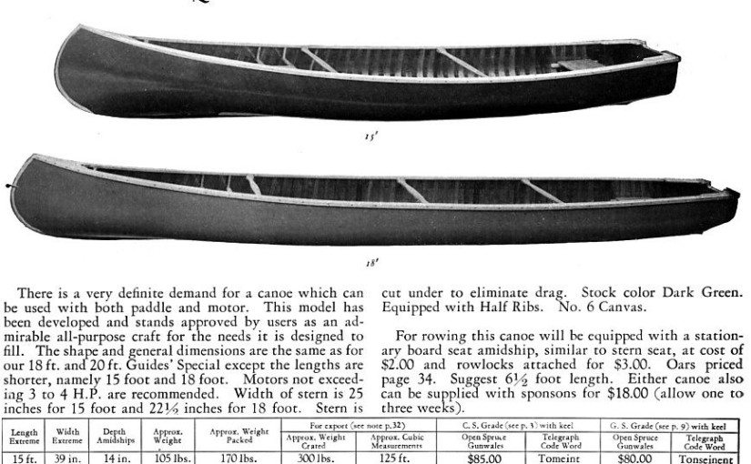
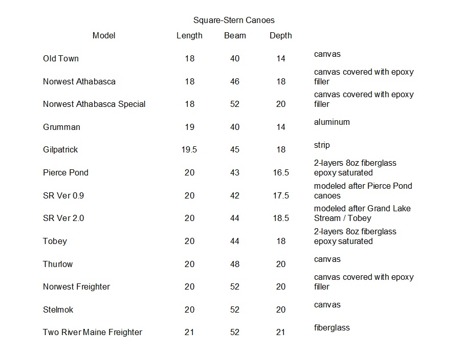
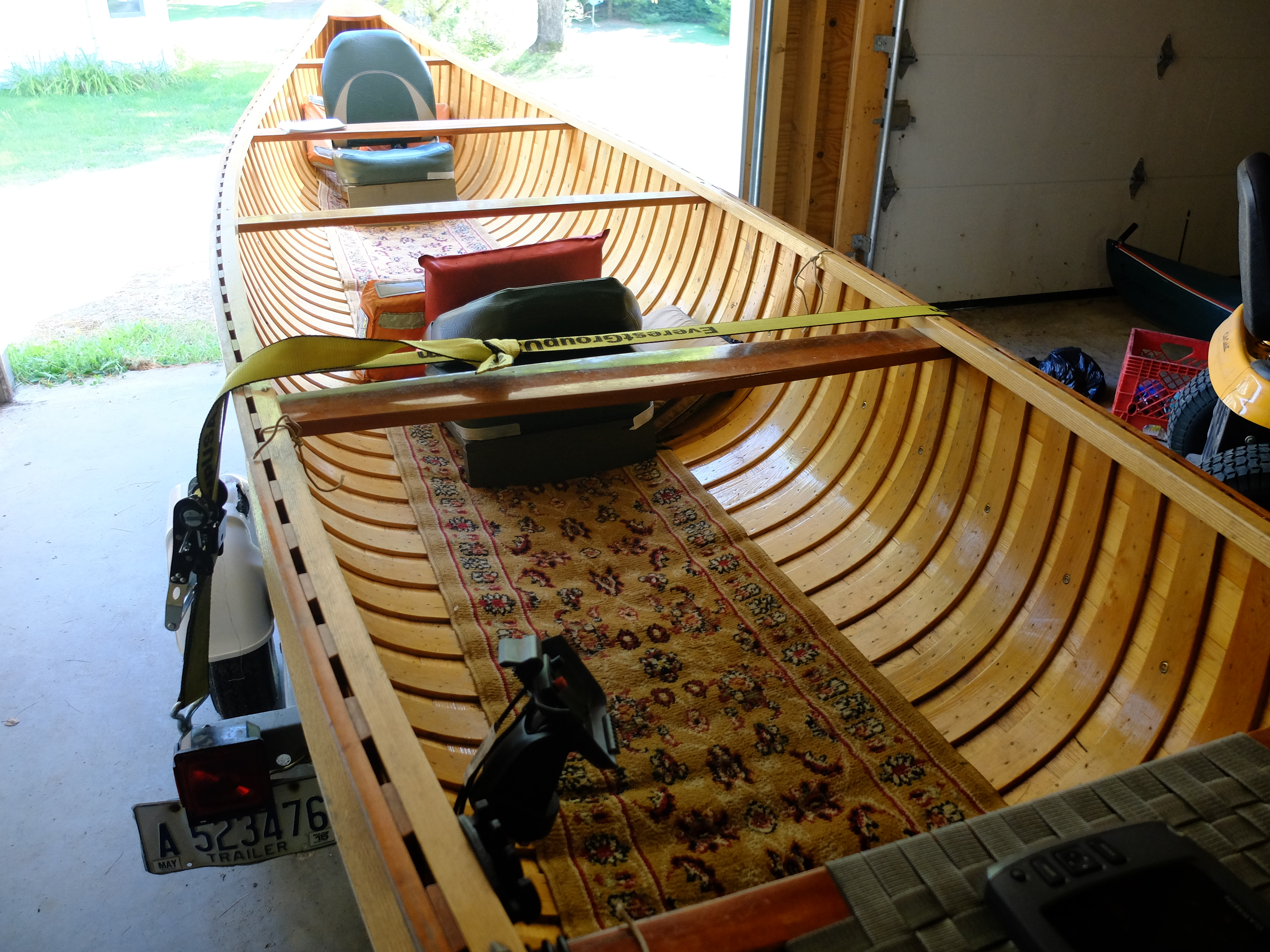
When we went, we weren’t sure we would even be able to canoe on the ponds for an afternoon since they are entirely privately owned, as is the access road. We went there on a hunch we could get in, having a day free after a canoe trip on Flagstaff Lake. Least of all did I expect to be measuring boats – so it was a very pleasant surprise not to be turned away at the gate but instead allowed in for a nominal fee, and the guides with canoes we met were not unwilling to talk about the boats. I used a stick to take rough measures of one of the boats, and got two pieces of information from one of the guides – the transoms are now about 24″ wide, and the maximum girth was somewhere around 5 1/2′ gunwale-to-gunwale. When we got home I transferred my stick measurements to feet and inches and came up with a boat 20′ long, 42″ wide to the outside of the planking, 16 1/2″ deep inside, with a transom 16″ tall by 22″ wide and a stem about 27″ tall from the outside of the bottom. These dimensions were the beginning of my collection of dimensions from which I am now working up a set of offsets.
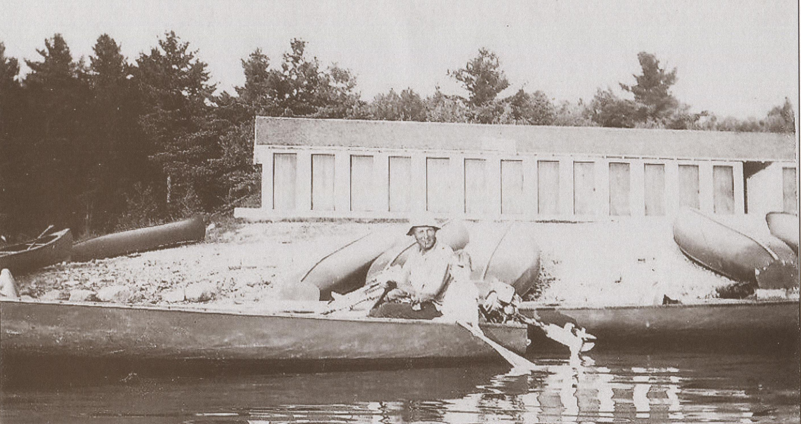
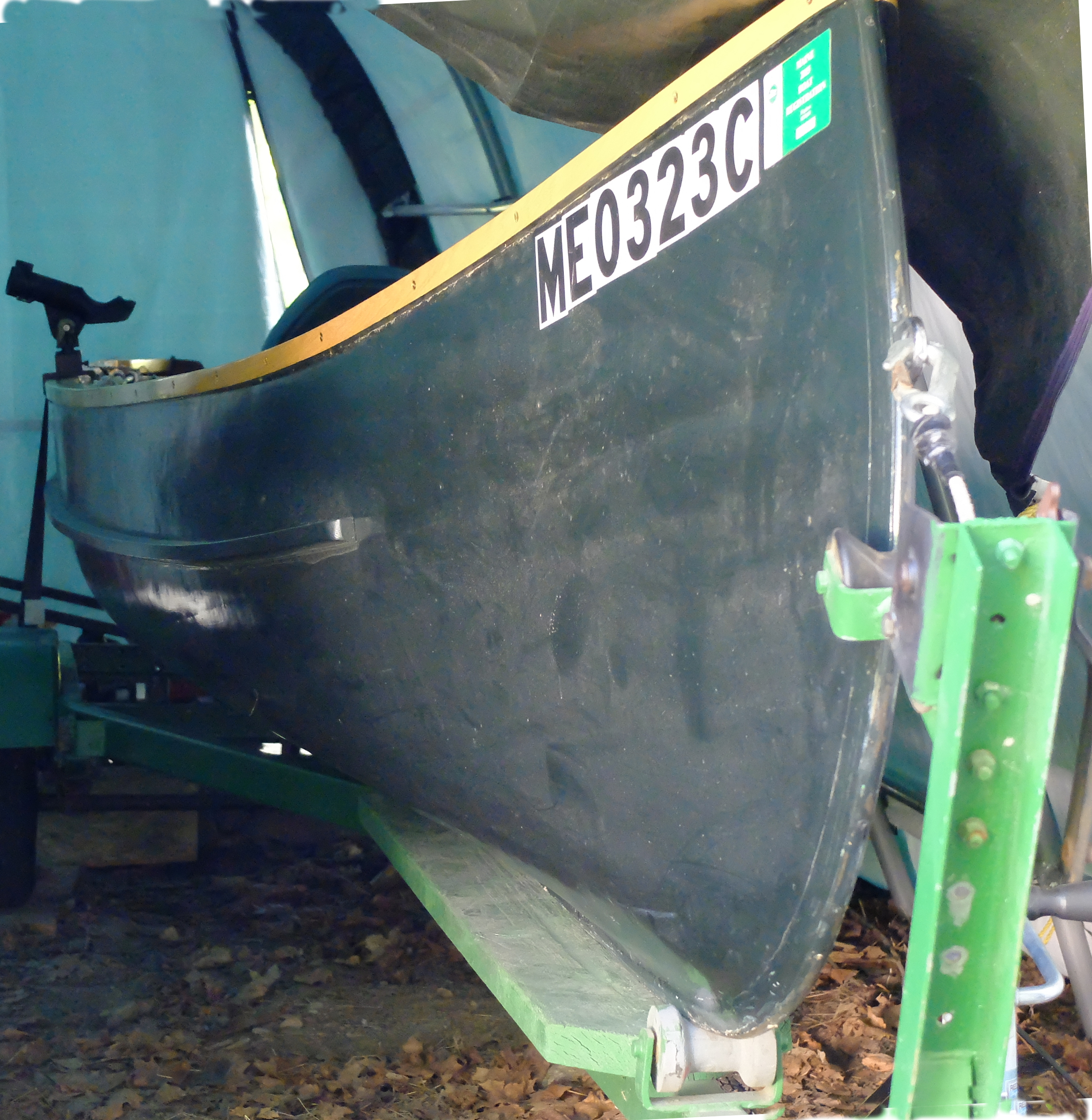
One of the guides told us that the boats were mostly built locally, developed from one boat brought down from Grand Lake Stream, and that his father built most of the boats, and still had the mold. The boats we saw were traditional cedar/canvas construction, except now fiberglass-covered, as I assumed they would have to be given their heavy use. The youngest boat in the camp was 15 years old. Motors were typically 5 HP 4-stroke, but 2-strokes were still in use up to 15 HP.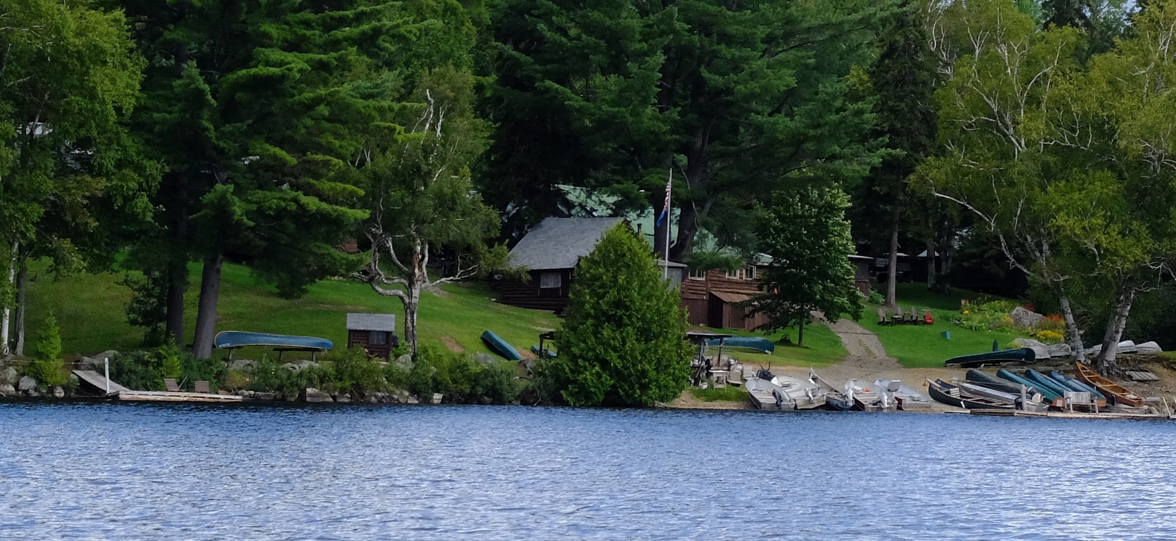
I worked up a set of offsets from the dimensions I had, drawn at 1/8 scale. Briefly, the offsets represent sections taken perpendicular to the length of the boat that are cross-sections of the hull along its length. They become the shape of the mold on which the boat is built. The drawings which are used to develop the offsets are views of the boat from three directions : End-on, from the side, and from above. These are called, respectively, the body plan, profile, and half-breadths.
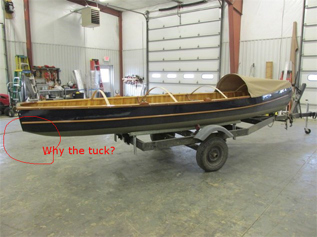
Looking at these boats, the maximum beam appeared to be somewhat aft of center, and carried aft more than forwards, to a quick taper at the stern. This made sense given that the motor might weigh up to 80 pounds, plus gas tank, plus guide sitting at the very stern of the boat (not to mention the 12-pack).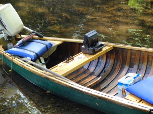
I had enough information to lay out the profile view and the sheer line of the half-breadth view. I marked 10 stations, with #1 and #10 at 1′ in from the bow and stern, and the others 2′ apart for a total length of 20′. I assumed a very slight rocker to the keel, and a rake of 2″ on the transom. I could now start the body plan, taking the sheer heights for each station from the profile view, and the widths from the half-breadth view. For this stage, I also assumed a pretty flat bottom with gentle curves through the turn of the bilge, a little flare in the forward sections and a little tumble-home in the aft sections. After drawing up sections that seemed reasonable, I took the measurements of each station off the 1/8 drawing and expanded them and redrew everything on a 11′ x 20″ piece of plywood to get a half-size drawing.
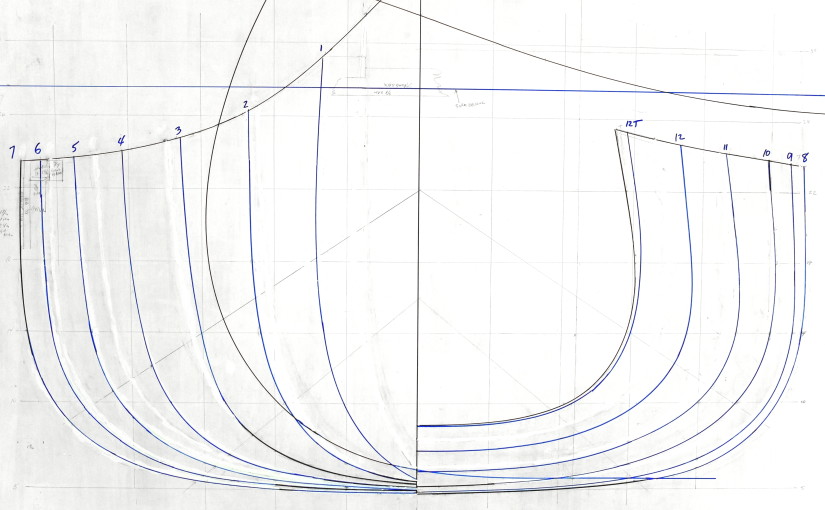
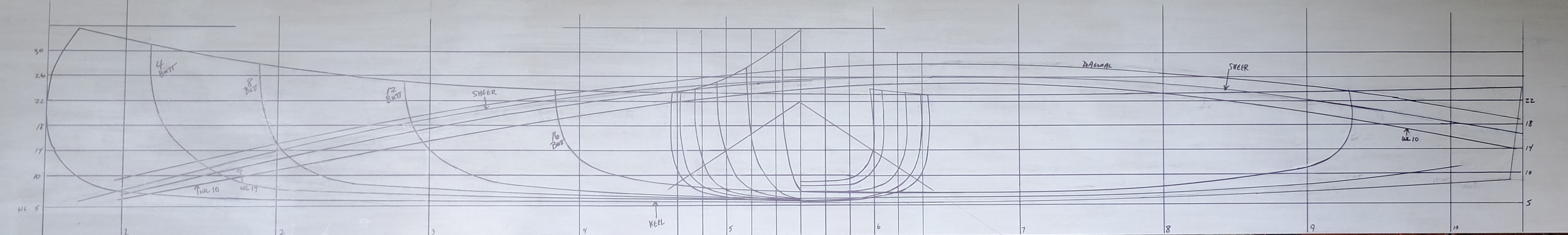 Howard Chapelle’s book Boatbuilding has an extensive explanation of the process of lofting; the purpose of lofting the boat, which means drawing out the shape in full size or some easily-scaled fraction of full-size, is to assure that the shapes of the sections, when assembled on a form, will produce fair curves without bumps or dimples. (this is a major over-simplification) It is easy to picture 3 sections which, when viewed end-on as in the body plan in the middle of the drawing above, appear to be smooth transitions one-to-the-next – but, when actually placed in their respective locations on the building form, do not produce smooth curves at all. Lofting is intended to identify this error and provide a method for fixing it. If you purchase a set of offsets that has already been lofted and corrected by the designer, you don’t need to go through the lofting process; you just have to draw out the sections.
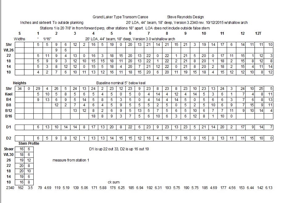
In my plan above, the vertical lines on the body plan are called buttocks and represent vertical slices through the hull running the length of the boat. The horizontal lines in the profile view are called waterlines and are horizontal planes running through the hull parallel to the keel. The reference points which define the shape of the stations in the table of offsets are : Half-breadths (widths) to the station at each waterline, and heights to the station at each buttock. The ‘diagonal’ is a diagonal line through the sections at an arbitrary location. The table of offsets for the design above is :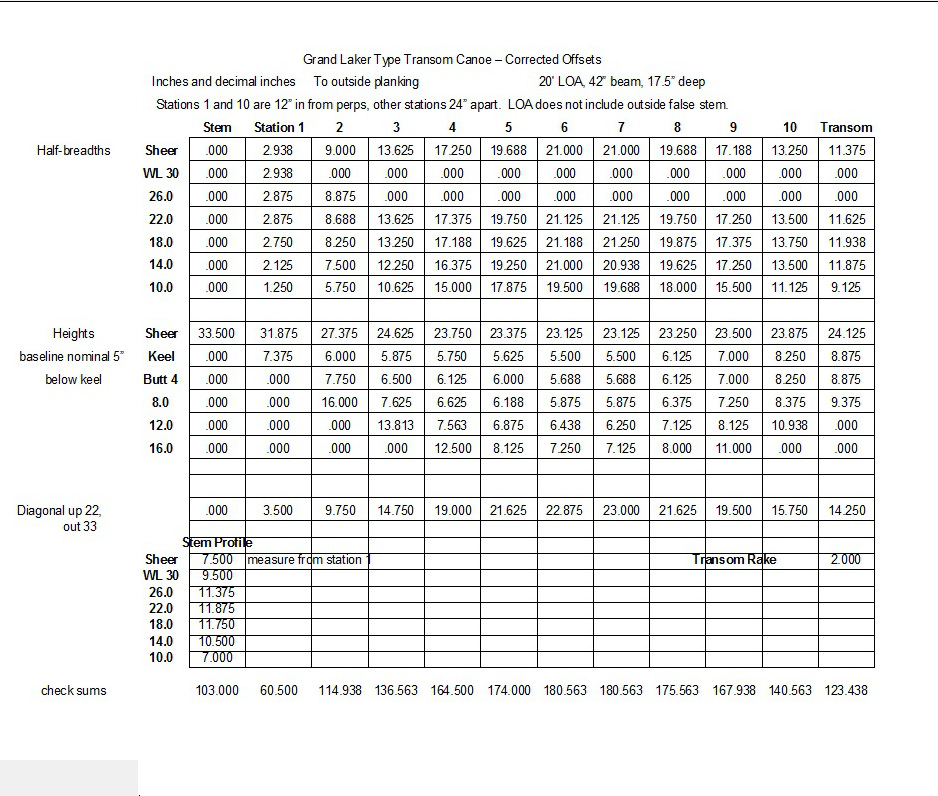 Lofting takes each point along a given reference plane and plots them on the drawing to see if they can be connected with a fair curve. For example, waterline 18 goes from 2.75 inches at Station 1 to 11.938 inches at the transom. Drawing this line out will show which stations are out of fairness, and need to be corrected. Lofting this plan meant drawing out all the waterlines, and the sheer, as well as all the buttocks. The offsets above have been corrected for fairness.
Unfortunately, I next discovered I had drawn a boat that was not representative of a typical Grand Laker, and I had to start again. To be continued.
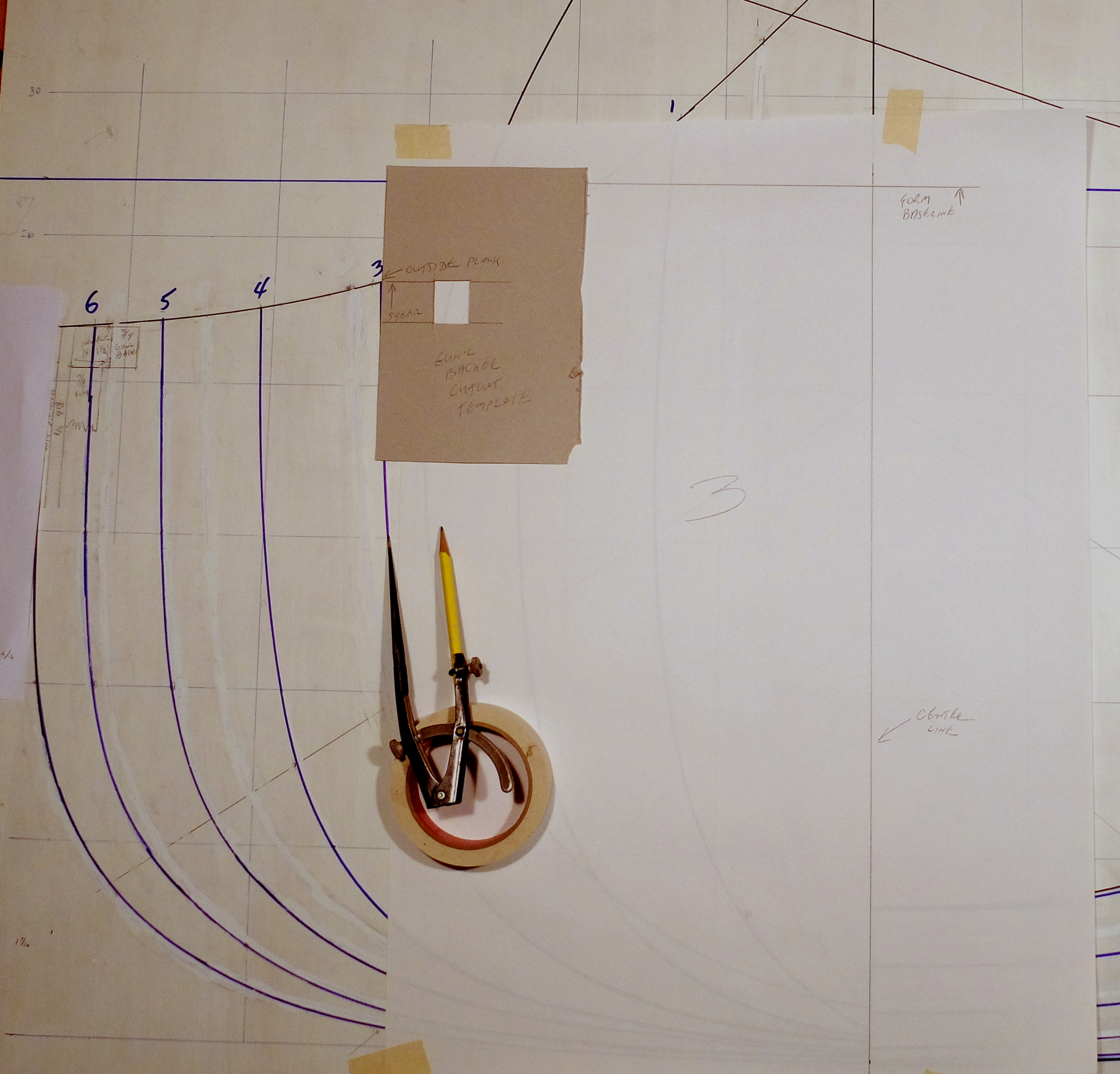
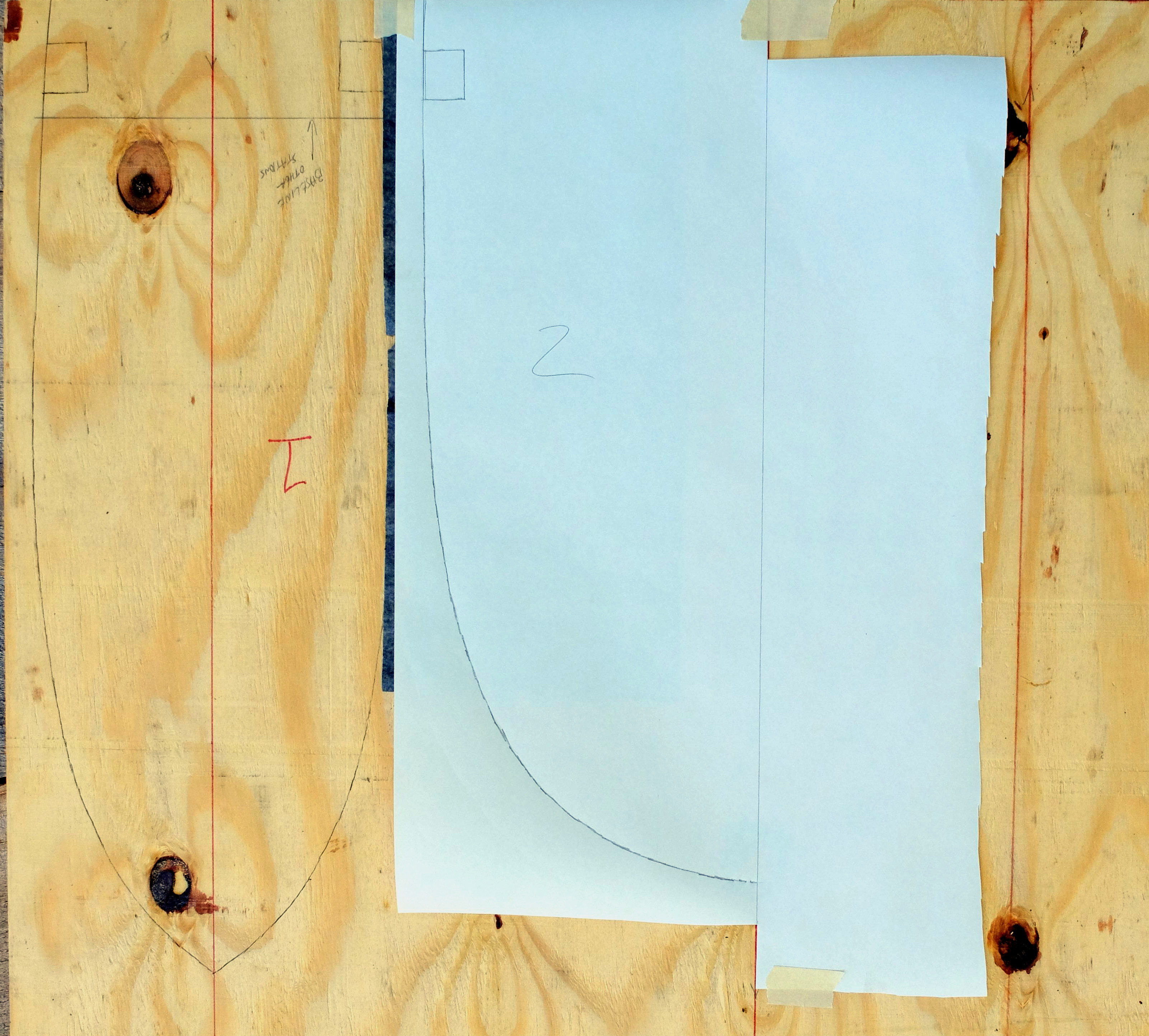
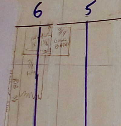 Picking up the shapes of the form molds from the body plan – The body plan is drawn to the outside of the planking and the lines must reduced to get the shape of the plywood stations which make up the form. The total thickness of the reduction is: 3/16″ planking plus 3/8″ ribs plus 7/8″ form sheathing, or 1 7/16″. There is also a cutout in the form molds for a backer behind the inner gunwale, which will be 3/4″ x 1 1/8″. The form sheathing is clear pine strips 7/8″ x 1 1/8″ – I could probably have used 3/4″ but will try the 7/8″ for a more solid form, although it will make fixing some of the strips more difficult to twist into position.
 I set the dividers at 1 7/16″, hold them at a right angle to the curve of the body plan, and trace a line onto a piece of paper placed over the body plan. I can see the lines of the body plan through the paper. I draw in the cutout for the gunwale backer. I don’t trust the paper to retain is shape for days, so I transfer the new line right away to my mold material – 3/4″ CDX plywood.