There is only one published source of plans for a Grand Laker canoe that I know of, and that is in Gil Gilpatrick’s book ‘Building a Strip Canoe’. When I decided I wanted to build a square stern canoe, I started looking for plans and considered Gil’s but changed my mind when I could not find pictures of boats built from his. Instead, I drew up my own plans based on boats I measured. I am still interested in how these boats vary one from the other, and decided to work Gil’s plans up by lofting them and developing a table of offsets, so I could understand where his boat fits in the evolution in shape that these boats went through from their origins in the 1920’s until now. I hope I can add to the slim documentation of these iconic boats, and give his plans credit for documenting one phase of their development. Gil has kindly given me permission to publish my results in my blog, for which I am grateful.
My first edition copy of ‘Building a Strip Canoe’ has plans for a Grand Laker at 1/3 scale. The plans include outlines for 10 stations plus transom and stem profile, drawn to what would be the inside of a strip-built hull, but they do not include a table of offsets. While the plans as-is can be used to construct a form, I saw several reasons to loft them. Lofting would prove the fairness of the lines and allow me to measure any part of the boat I wanted.
Starting with measurements taken directly from Gil’s drawings, I would have to develop a table of offsets in order to do the lofting, but I would also have to make some changes and assumptions about the boat. Gil’s plans show each station through the boat at 20″ intervals along the length, in what would be called a ‘body plan’. However, the stations are not lined up so that the keel appears straight, but lined up in reference to a line running approximately from the top of the stem to a point about 5″ over the transom, which becomes the plane of the form backbone once the stations are assembled for the form. Thus, it is difficult to visualize the anticipated shape because the baseline is not parallel to the keel – making the boat appear ‘bow down’ in the plans. I would want to establish a new baseline parallel to the keel. Other minor problems included: it is unclear whether the station labeled ‘stern’ is the expanded shape of the transom, or the transom as it appears viewed directly from astern; the sheer line height at station 1 is not indicated; and, the space between each station cited in the plans, 20″, will yield a boat only 18′ 6″ (10 spaces plus 22″ stem projection) – whereas most Grand Lakers are 20′. I would spread the stations to 21 1/2″ to yield a 20′ boat, and loft that.
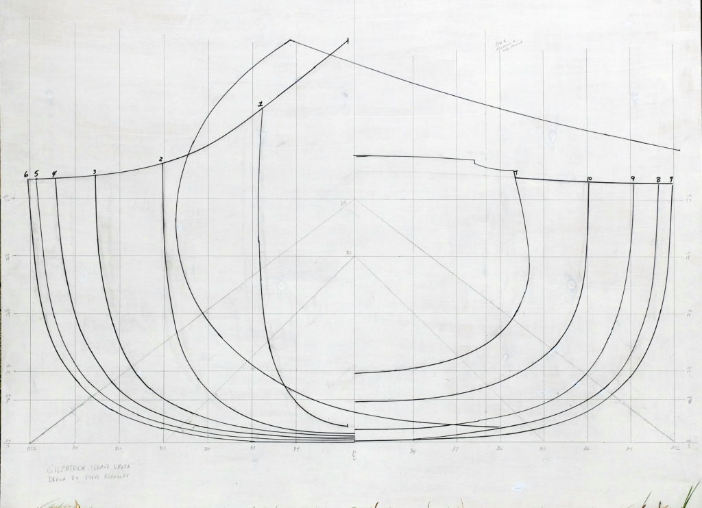
I established the overall slope of Gil’s baseline perspective to be 5 5/8″ over 200″, and then calculated the amount of vertical adjustment at each station necessary to level his drawing – the adjustment got bigger with every station moving from the transom to the bow. Taking measurements off his plans, I developed a table of full-sized vertical offsets at buttock lines spaced 3″, now corrected to a new baseline parallel to and 5″ below the keel. (Buttock lines are vertical slices through the hull running lengthwise parallel to the keel, as opposed to waterlines, which are horizontal slices running through the hull parallel to the waterline. The vertical lines below are buttock lines and the horizontal lines are water lines.) I used the vertical offsets to draw a preliminary body plan full size – rough draft, below. From this drawing I was able to measure horizontal offsets for my first stab at waterlines.
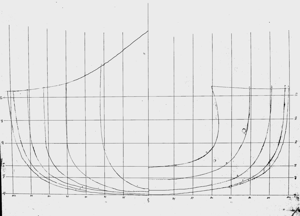
Referring to the above drawing – the baseline is 5″ below the keel for convenience of measuring. Waterline ‘5’ is therefore at the level of the keel, the next one up is WL8, then WL10, 14, 18 and 22. I chose these waterlines arbitrarily. I am interested in the underwater shape of the hull, and waterlines 8 and 10 will give me that information when lofted. The buttock lines proceed out from the vertical center line – the first is B4, and then they progress every 3″ out to 22″. The front half of the boat is on the left, the aft on the right.
Several observations about this design can now be made. The sides are nearly vertical in the forward third of the boat, with flare developing through the mid sections going to strong tumblehome only in the transom. Maximum beam occurs at station 6, which is just aft of center. The center section of the keel is nearly straight. There is about 1″ of rocker forward of station 3 and marked tuck in the stern aft of station 8. There is about 5″ to the tuck, going to a transom that is 13″ tall. The sheer is practically flat the entire way from the transom to station 3, where it begins an increasingly sharp rise to the stem. Maximum beam is about 45″ and maximum depth about 18″. The sections are moderately flat through the bottom and broadly rounded at the turn of the bilge.
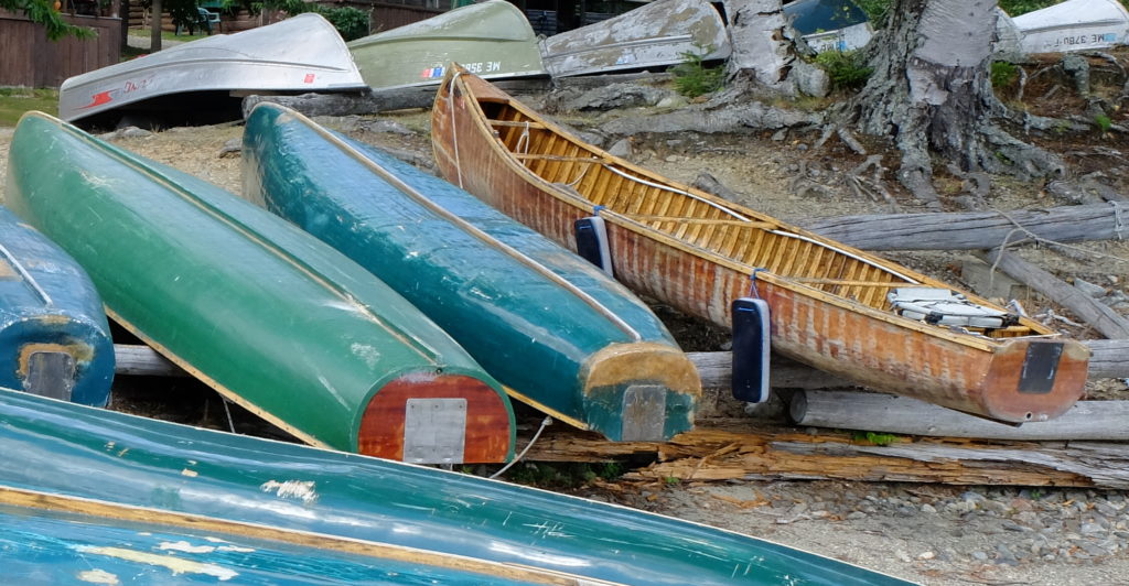
What boat is this? Gil drew these line 25-30 years ago. Now, he does not recall details of the boat that he copied except that it was probably 20′ long, and at some point the plans got changed to the 18′ 6″ length shown in his book. Without going out and measuring existing boats, the heritage of Gil’s boat is unclear, but it bears a strong resemblance, at least from photographs, to some boats I have seen. Here are some examples of variation in hull form.
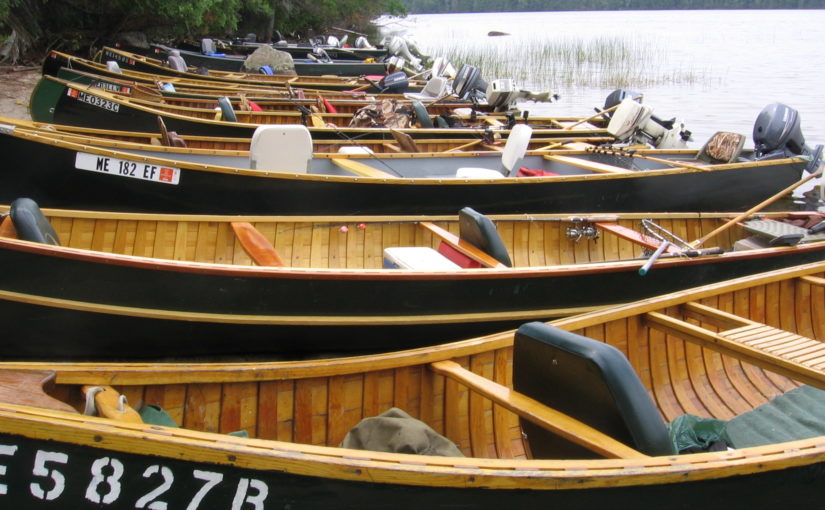
These boats were seen in western Maine. Gil’s boat looks a lot like the one on the right.
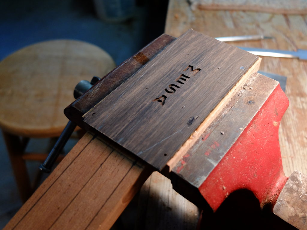
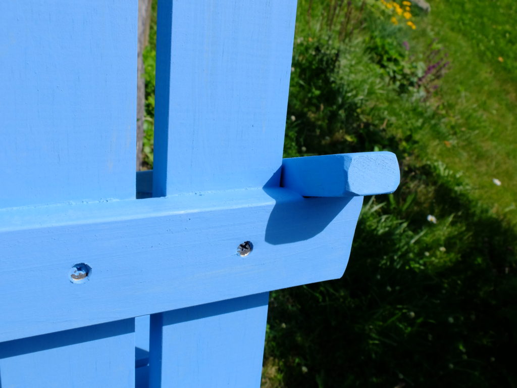
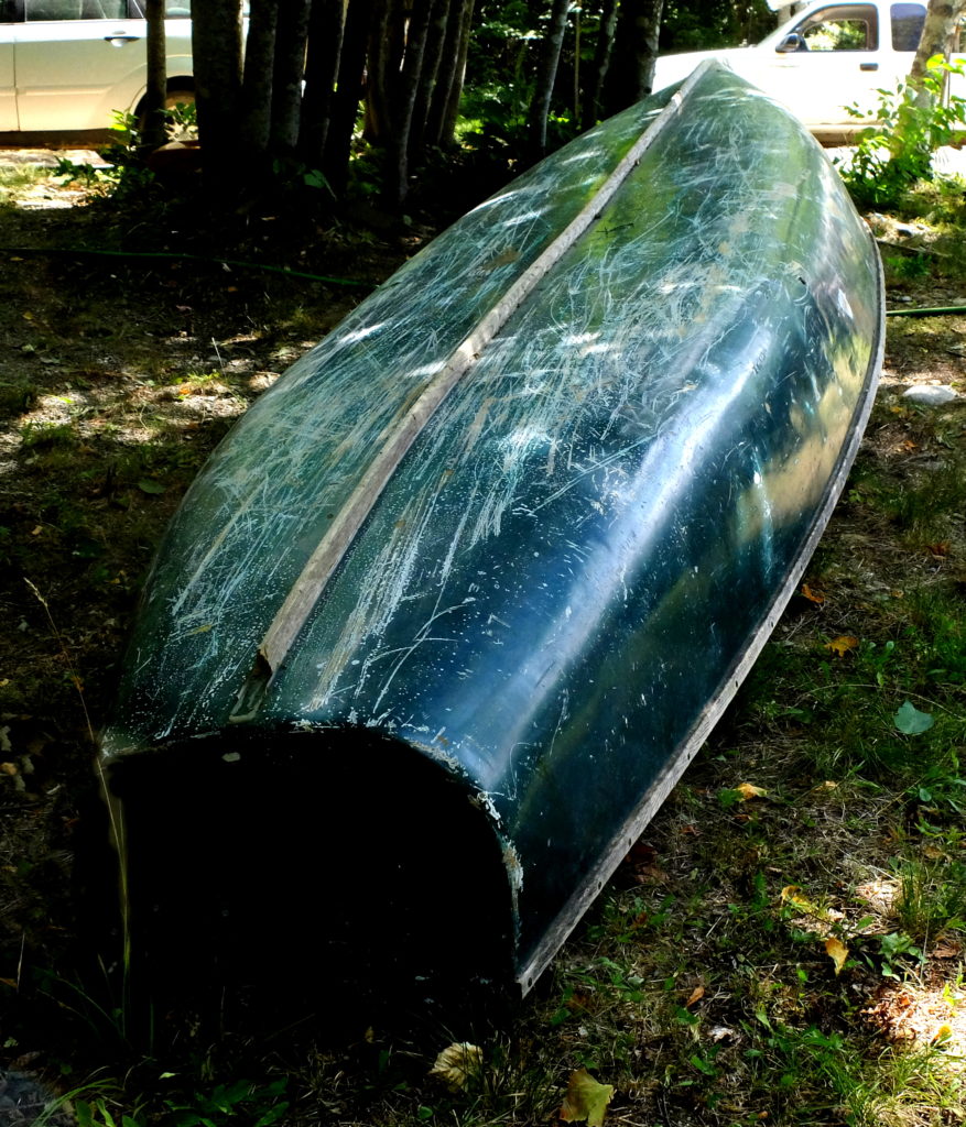
The middle boat is similar in the stern to the one on the right, but it is possibly flatter in the bottom than Gil’s. The one on the left is a different model – more rounded body sections, fuller transom. The 13″ transoms are raised above the sheerline by a riser to accommodate short shaft outboards that need at least a 15″ tall transom. This is a close up of a transom of another these boats showing the transom riser. I will add a transom riser to the lines I draw from Gil’s plans.![]() The western Maine boats in general show very flat sections. This one, at the dock, and the one below it, by the Gate House.
The western Maine boats in general show very flat sections. This one, at the dock, and the one below it, by the Gate House. 
 I believe they were built from a form derived from a boat from Grand Lake Stream, and they seem to be mid-way in the evolution of the shape that started with a large canoe with the stern cut off, and the more recently built boats that are intended for larger motors. The youngest of these boats is now 15 years old. I believe they represent one branch of the Grand Laker family as it was some time ago. Newer boats show larger transoms built on forms that were probably modified for that end. This is a Pop Moore boat built in 2011 at Weatherby’s Lodge by Bill Shamels which shows almost no tuck in the stern, compared to boats built at Grand Lake Stream in the 1930’s.
 More recent boats like this one by Dale Tobey combine rounder and deeper mid sections, larger transoms and less pronounced tuck.
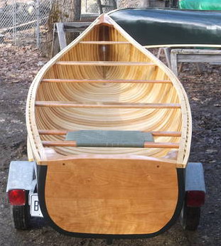
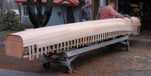
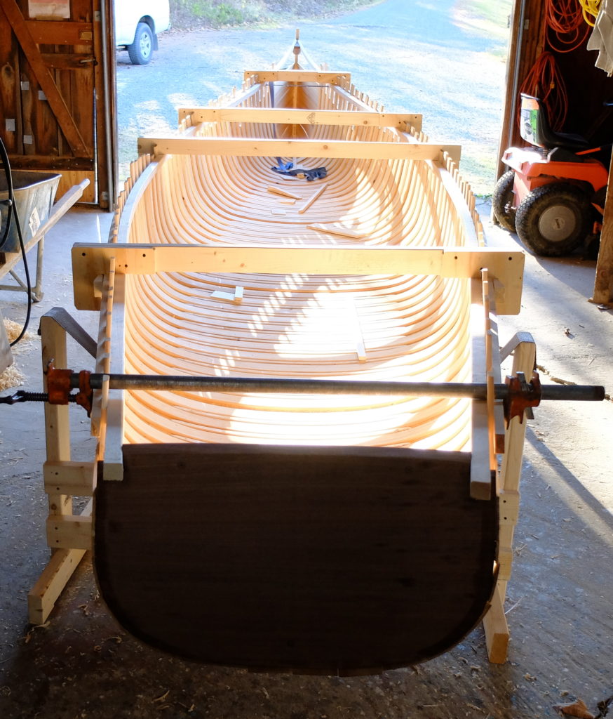
Finally, for comparison, I have mine (under construction). A little flatter in the middle and sharper in the bow.
 Lofting entails drawing out the shape of a boat full size, or at some appropriate fraction of full size, and connecting the stations with lines to prove that a smooth curve can be produced from one station to another along certain selected sections. For instance, a line connecting all the stations where their outside surface hits waterline 8 should be a smooth line. The purpose of lofting is to assure that a smooth hull can be produced, and also to provide a representation of the boat that can be used to measure other shapes.
Lofting produces three views of the boat – the body plan (as shown early in this blog entry), a profile or elevation plan, which is the boat viewed from the side, and the half-breadth plan, which is the boat viewed from above. The drawing below includes all three views showing the lines of a square stern canoe I drew based on the western Maine boats.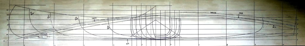
During the process of lofting, decisions have to be made as the need for corrections arises. In the case of Gil’s boat, I had to decide whether I was going to try to ‘improve’ the design as well as fair the lines, and I decided I wasn’t, except for length. ‘Lakers’ are almost universally 20′ long or close to it, and I adjusted the spacing of the stations to accomplish that. If I were to otherwise try to improve it, I would give it more sheer in the stern and more graceful sheer in the bow, less tuck and a higher transom. In order to preserve the documentary value of his plan, I decided not to do that, and just fix what seemed like obvious errors. Where I could not get things to line up smoothly, where the faired lines gave notably different measurements than I got off the plans, I worked with what seemed to be the majority of the points involved and adjusted the outliers. This happened in the bow sections mainly. I could not get the full bow to fair smoothly with the rest of the hull, and so sharpened it a little. I placed the ‘stern’ station vertically, 3″ in from the aft perpendicular, and left it to the builder to determine the real shape of the transom, which is raked about 2″ in 15″.
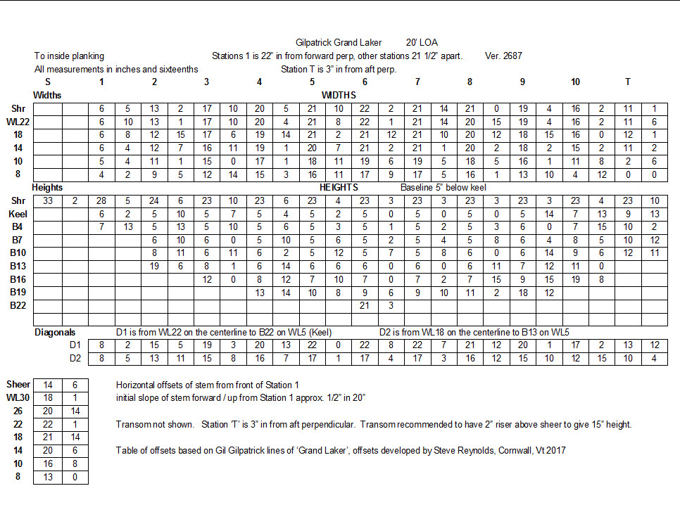
I now have a table of offsets for the lines I drew from Gil’s plans –
 and a body plan at full size, after lofting the profile and half-breadth plan at 1/3 size. If you want to compare it to Gil’s plans, you’ll have to buy his book.