Many parts of the construction trades are a matter of learning how to do an essentially simple task, and then repeating it. Some or many tasks involve special knowledge and training, or strength and agility, and those can be hired out, but many many things can be done by people of normal facility. I also appreciate the risks that devolve from incorrect construction decisions or practices and avoiding certain mistakes may require study and experience – and – it may also require one to ignore advice offered by experts – in short, a good dose of skepticism. In the current environment where labor costs exceed hundreds of dollars a day per worker, people can do things for themselves that produce real results which they could otherwise afford only with difficulty, or possibly not afford at all. In this category I put a home. I have been lucky to be able to work with my son building his home and more recently a recording studio for his professional use. Doing well over half the work ourselves has literally saved a couple hundred thousand dollars. (the reason my blog has appeared inactive for the past many months is a direct result of my involvement with these projects)
Building out the basement of his home as a studio was a 2 year project. Towards the end of the project, we had important assistance from a carpenter friend who handled most of the ‘acoustic treatment’ on the walls and ceilings, but otherwise my son and I did all the work except for the wiring and HVAC system, which were hired out. We are generally well versed in standard construction practices, but there are many peculiarities specific to recording studios and my purpose is to discuss these in this blog for the unlikely few who may be trying to do something similar.
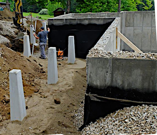
Beginning with the foundation of the house, we took steps to ensure that the basement would be dry. These were to provide damp-proofing to the concrete, cover that with a dimple mat drainage plane like DELTA-MS Below-Grade Foundation Protection, use lots of coarse gravel backfill, and provide perforated collection drains at the level of the footers going out to daylight. The site, being on a hillside, facilitated drainage. In the picture below you can see the damp-proofing, dimple mat and backfill; the drainage pipe is already buried.
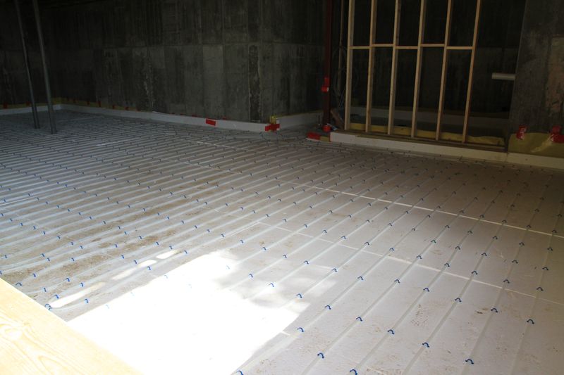
Inside the basement, the slab was poured to include radiant heat supplied via PEX piping. The floor was first leveled with coarse gravel and compacted, then covered with a heavy poly vapor barrier of STEGO® WRAP VAPOR BARRIER (15-MIL). The seams in the Stego Wrap were sealed with waterproof tape, and the wrap was brought up the side walls above what would be the top of the slab. The poly was covered with 3″ EPS foam insulation board to which the PEX tubing was stapled. The foam board was wrapped around the perimeter to finish higher than the top of the slab.
The way we did the prep for the slab was an instance of going against the advice of an expert, the expert being Joseph Lstiburek of the Building Science Press. He is adamant that a vapor barrier, when used in a slab in conjunction with foam insulation, be on top of the foam and not beneath, his reasoning being that foam will absorb some water, and should there be any leakage of moisture up through the poly, the foam will eventually become saturated and emit continual moisture into the building if the vapor barrier is below the foam. Lstiburek didn’t account for how to fasten PEX to the foam, and he didn’t plan on having to argue with the contractor we hired to pour the slab, so he lost, and now, 3 years into owning the thing, there is no problem. Just a case where theory had to bend to reality.
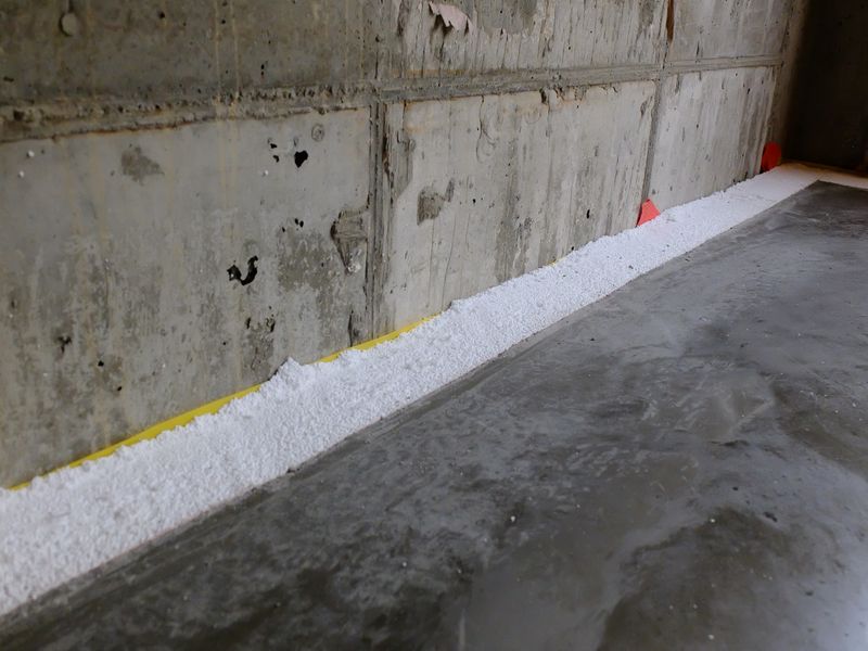
After the slab was poured, we had to go around and cut back the insulation sticking up around the perimeter. Picture of foam after being cut back.
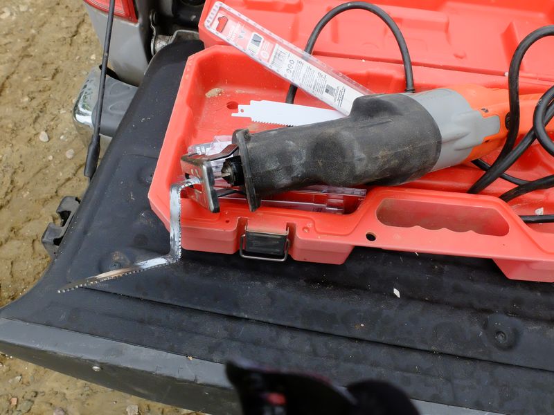
I made a custom blade for my Sawzall that helped a lot.
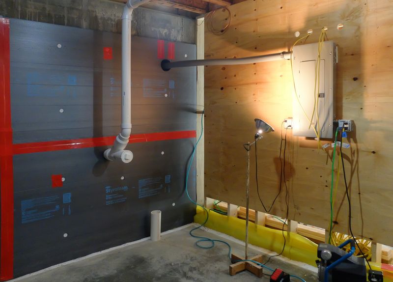
The next step was to cover the entire interior of the foundation with 1-1/4″ XPS foam board, starting with the top, taping all the seams and making our best effort to minimize interior air contact with the concrete to control condensation. After encapsulating the concrete with the foam board, including the top, we had the rim joist spaces spray-foam insulated. This was the only application we had of spray foam in the house. The XPS foam was attached with PL Premium construction adhesive and a minimal number of foam concrete anchors to hold things in place until the adhesive set up. This picture shows a portion of the machine room wall with the XPS attached and taped. You can also see the Stego Wrap and perimeter foam EPS in the floor.
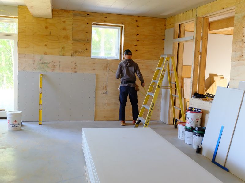
The studio enclosure is essentially a free-standing room within the basement. The design by Martin Pilchner of Pilchner Schoustal Inc Architectural Acoustics specified wall and ceiling assemblies to be 2″ thick, consisting of a layer of 5/8″ sheetrock covered with a layer of 3/4″ plywood covered with a layer of 5/8″ sheetrock. The middle layer of plywood provides an uninterrupted surface on which to attach lights/acoustic treatment/etc. The walls were built on a 2×4 stud wall spaced 2″ in from the XPS foam-faced concrete, framed 12″ on center with horizontal blocking every 4 feet. The bottom plates of the walls covered the junction between the concrete slab and the inner edge of the perimeter foam, and were glued to the slab with PL Premium construction adhesive. We used pressure-treated lumber for the plates as a precaution against any moisture movement up through the concrete. All structural connections were made with screws; the only nails in the entire project were to attach finish trim at the end. All joints were also given the PL Premium treatment.
The walls and ceiling are not directly connected overhead to the joists. Instead, they are connected to the metal framing suspended from the joists which holds the ceiling. The metal framing ‘hat channel’ is suspended from sound isolation clips (RSIC clips) spaced every-other-joist in rows 12″ apart, and the hat channel, where it meets the side walls, is attached to an ‘L’ bracket that connects to the walls, tying everything together. These RSIC clips provide acoustic de-coupling between the studio and the surrounding structure.
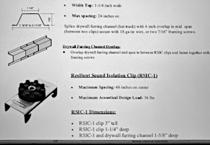
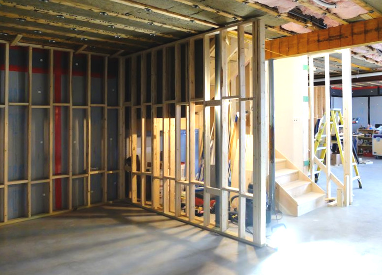
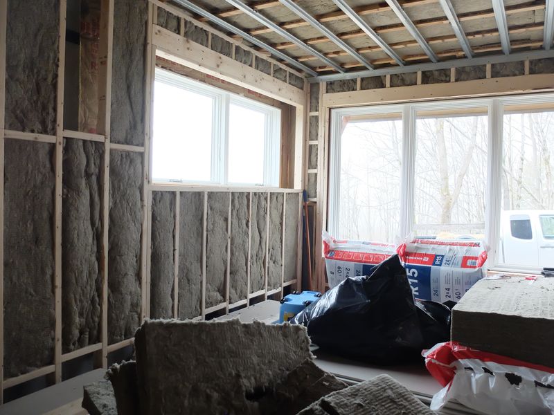
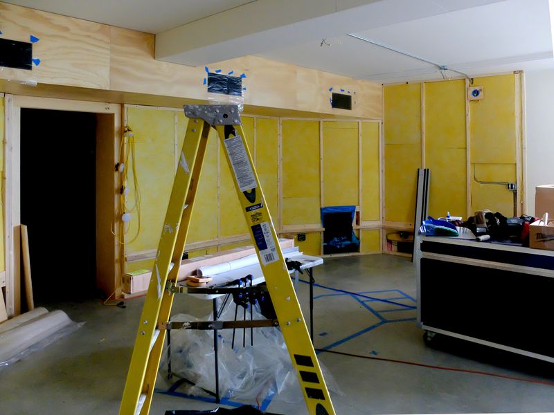
We met several challenges with the clips and metal framing. First, laying out the clips on the ceiling was vastly facilitated by, or, otherwise nearly impossible without, a laser level that projected a plane of light in a vertical dimension along the underside of the joists. Second, it took some serious calculation to assure ourselves that we could hang what became 3-1/2 tons of sheetrock and plywood from the screws which hold the clips to the joists, and that the joists would accommodate the additional load. Thirdly it was somewhat of trial to find which screws worked with the 25 gauge hat channel, when some clearly and badly failed and stripped. The spacing of the clips in our case was 32″ x 24″. The studio is roughly 22′ x 42′ and there are about 344 clips, so each one is carrying roughly 20 pounds; they are rated a 36 pounds for clip spacing 48″ x 24″ so we were good there. Each clip is held to the joint by a #10 x 2-1/2″ GRK construction screw, which meets the design spec, and we had a structural engineer verify that the joists – TJI’s in our case – could handle the load with a maximum deflection of 1/2″. The screws used in the hat channel that worked were like a sheetrock screw, specifically bugle head fine thread streaker point. Self-drilling screws would work in heavier gauge metal framing, but with the 25 gauge channel, self-drilling screws just stripped and failed. The house and studio are hot-water radiant-heat supplied by PEX piping in the ceiling and walls and we were conscious from start to finish about the screw lengths we used and the need to avoid penetration into the wrong places. Below – walls framed, RSIC clips installed, no hat channel. Tube of PL Premium on bench. Piles of sheetrock waiting to disappear.
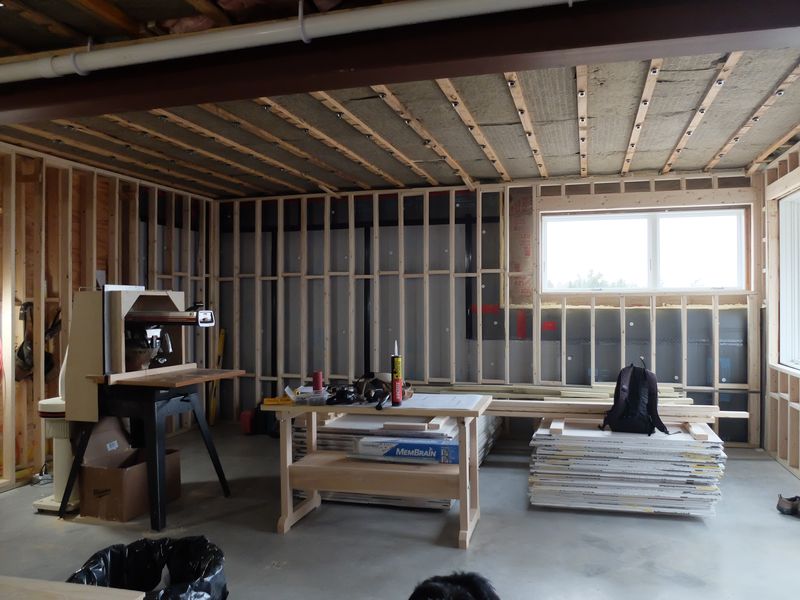
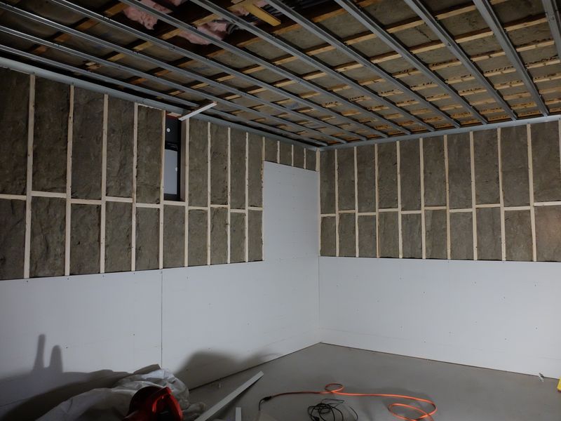
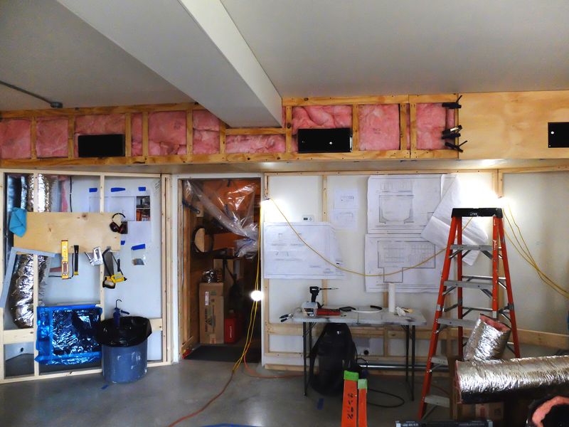
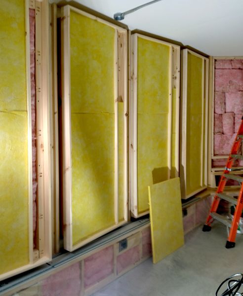
The walls and above-ceiling joist bays were insulated with mineral wool. Hat channel in place connected to perimeter L bracket.
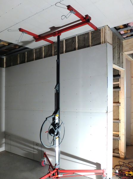
The wall and ceiling panels went on with staggered seams, screw-fastened every 6″, and the sheetrock seams were taped (but not finished) in the underlying layer. A sheetrock lift was absolutely necessary – we bought one for less money that we could have rented it, and sold it for half what we paid when we were done.
We did not put any wiring into the perimeter wall – simply because we couldn’t plan that far ahead. We assumed we would do surface wiring of some kind, which turned out to be true. But we could have made things a little easier had we planned some conduit into the wall structure – which was added later with a little more trouble. Ditto for wiring for audio gear.
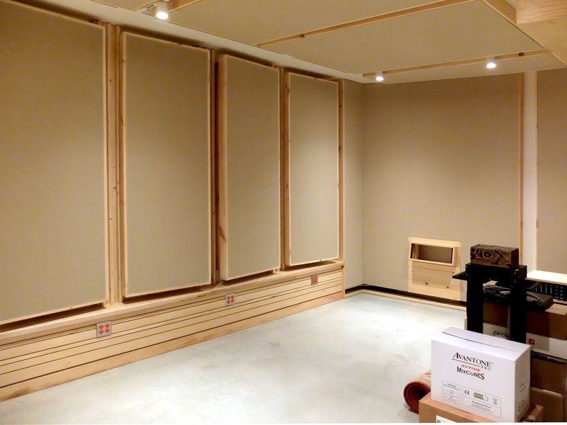
The plywood and sheetrock eventually come to an end. We didn’t realize at that point that about 80% of the ‘finished’ wall/ceiling would get buried under acoustic surface panels, so we (I) spent more time doing a nice clean spackle job in places that will never see the light of day – but – oh well – I remember it as a major personal milestone, almost like graduating from college, when I finished the last inner spackle corner and turned it over to my son to paint.
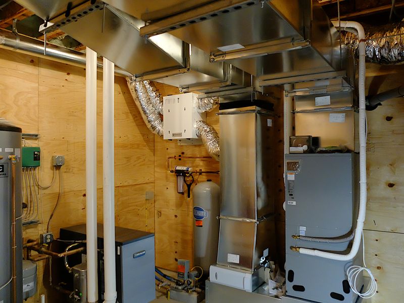
About this time we tried to settle on HVAC. Like the wiring, it was too much for us to plan ahead or make the decision on what kind of system to use before getting the basic structure in place. Initially, we had planned a mini-split heat pump with 2 wall-mounted air handlers and ended up rejecting this solution because a) it didn’t handle the disposal of condensate from cooling without electric sumps, which we thought a liability, b) it didn’t provide for any outside air exchange and c) they tend to be noisy. We ended up with a ducted system with an outside heat pump compressor, interior air handler, acoustically dampened commercial grade ductwork, and an ERV attached to the air handler. The whole system of ductwork is oversized to operate at low volume air flow and thus reduce noise. Below, right to left : air handler, return air plenum, ERV. The ERV differs from an HRV in that ERV’s are supposed to handle moisture exchange as well as heat exchange; whether it does or does not, hard to tell. The ERV takes return air out of the return duct and exhausts it to the outside; incoming fresh air is then dumped back into the return duct downstream of where the exhaust is extracted. The ERV operates according to the programming of the Ecobee thermostat. We have it running 10 minutes every hour, regardless of whether the heat pump is on or off; when the ERV is turned on the air handler is also turned on circulating fresh air.
The ductwork – fresh air into the control room part of the studio at the ceiling, return air from square ducts at floor level.
Electrical wiring was a major concern primarily from the point of view of avoiding radio frequency interference (RFI). Without knowing exactly causes or preventions, we knew that buzz happens and can be elusive and/or expensive to track down and fix. The electrical contractors we sought help from were sympathetic but also not experienced in recording studio wiring issues per se. We took advice and precautions that got us a dead quiet system; these were the steps we took: We run all the studio power from a sub-panel attached to the main house panel, and this gives us the option of providing a physical break in the wiring via an isolation transformer (I know, the word ‘isolation’ is redundant here since transformers inherently provide physical wired isolation). We don’t need the transformer now, but can add it easily in the future. We kept power and audio cable physically separate and did not run them in the same conduit. Where power and audio cables had to cross, we tried to make is a 90 degree crossing. We removed all lighting dimmer switches from the house because past experience showed that dimmers running standard LED bulbs can create RFI. The wiring is cable type MC metal clad which inherently provides an electrical shield to ground, and outlets are hospital grade. The house ground is both to outside ground rods and to the foundation reinforcing rod – a Ufer ground.
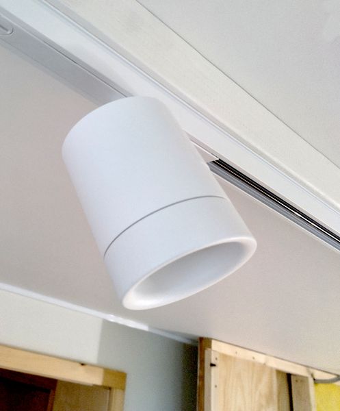
The lights are Philips Hue Perifo track lights – these are LED that have proven to be compatible with audio gear.
With the basic wall/ceiling assembly complete, finishing steps were to hang doors, install the double window providing sound isolation between the two rooms, install the acoustic treatment and wire the audio patch panel.
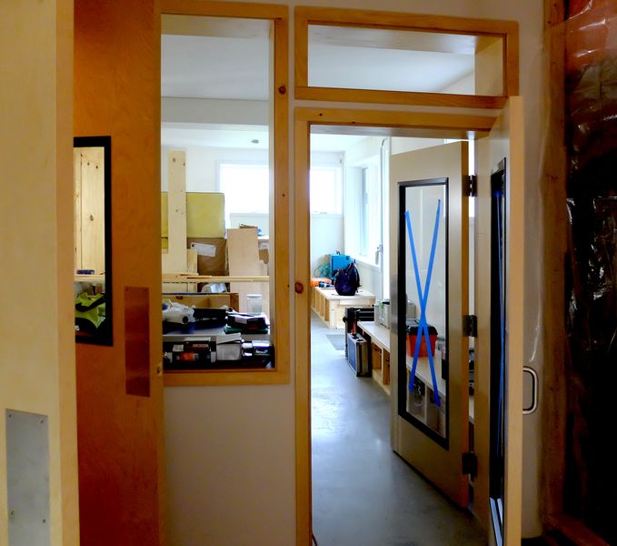
Doors are commercial grade hardwood solid core from CDF. The seals on the stops are a rectangular neoprene with a self-stick backing, and we used automatic door bottoms like the ones from Acoustical Solutions. The double doors and double glazed window, above, provide sound isolation between the control and the tracking room.
Acoustic treatment covers about 80% of the interior walls and ceiling. Basic assembly is a frame about 3″ deep, filled with 2 one-inch layers of Owens-Corning 703 semi-rigid fiberglass. The panels are covered with fabric set in Fabricmate fabric track. This was a touchy learning experience – setting the track in the frames and installing the fabric. It came out well thanks to our carpenter friend who quietly took control and just produced results. Thanks Lars.
In the control room, the finish walls are built out from the enclosing structure particularly in the corners aka ‘bass traps’ which are filled with normal fiberglass insulation behind the fabric panels.
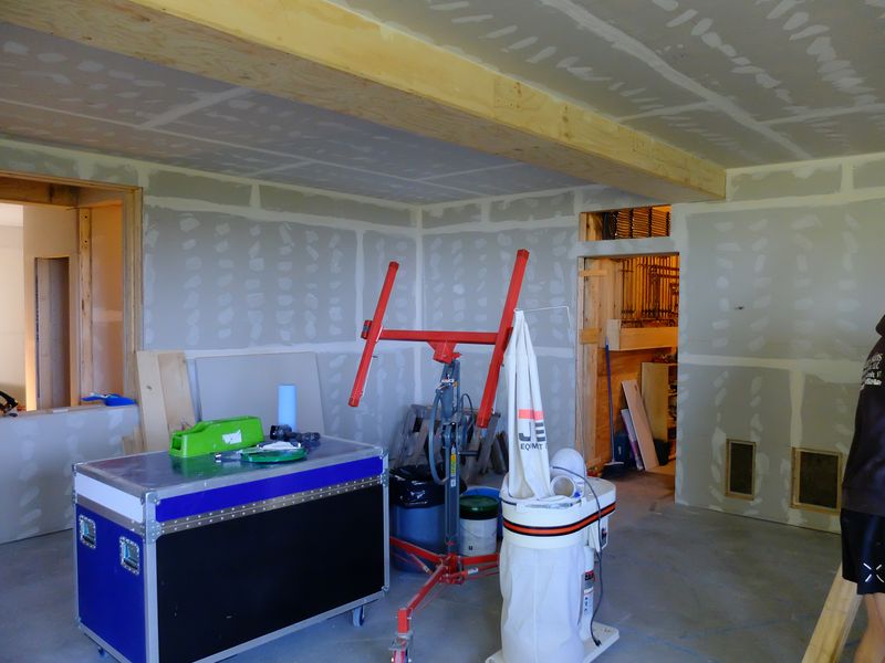
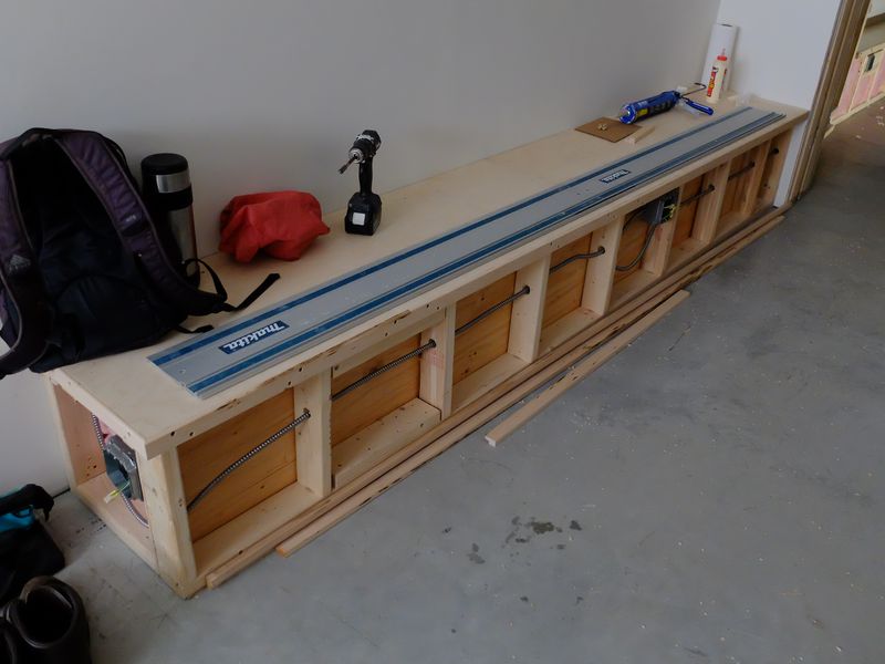
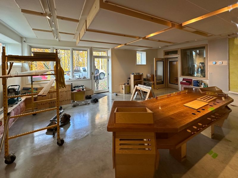
The last major job I had was to build the console. The plans looked like something that should be on the Space Shuttle. We came to like working with 3/4″ Baltic Birch plywood for different things including door casings and I used Baltic Birch for most of the console. The top is made of 2 pieces epoxy-glued together: a 3/4″ cherry finish face and a 3/4″ Baltic Birch backer. Both are WEST epoxy-encapsulated to retard or eliminate moisture transfer and thus cupping/warping, and to date the top has remained flat, as hoped. The pieces on each end are the gear racks where some of the audio and patch panels are located.
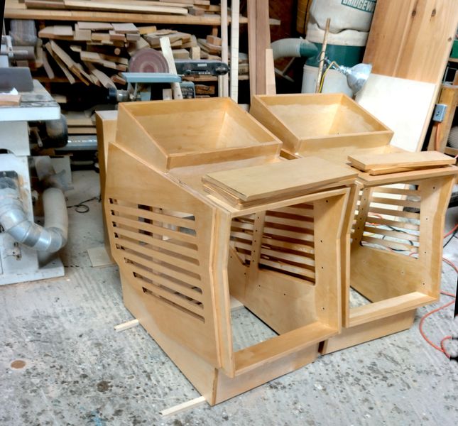
With the top assembly, the thing weighs somewhere around 150 pounds and is almost 12′ wide. We used an automotive jack to maneuver it into place.
I didn’t realize when I started working on it that I had a schedule to meet – getting it installed was a prerequisite to getting the audio gear wired.
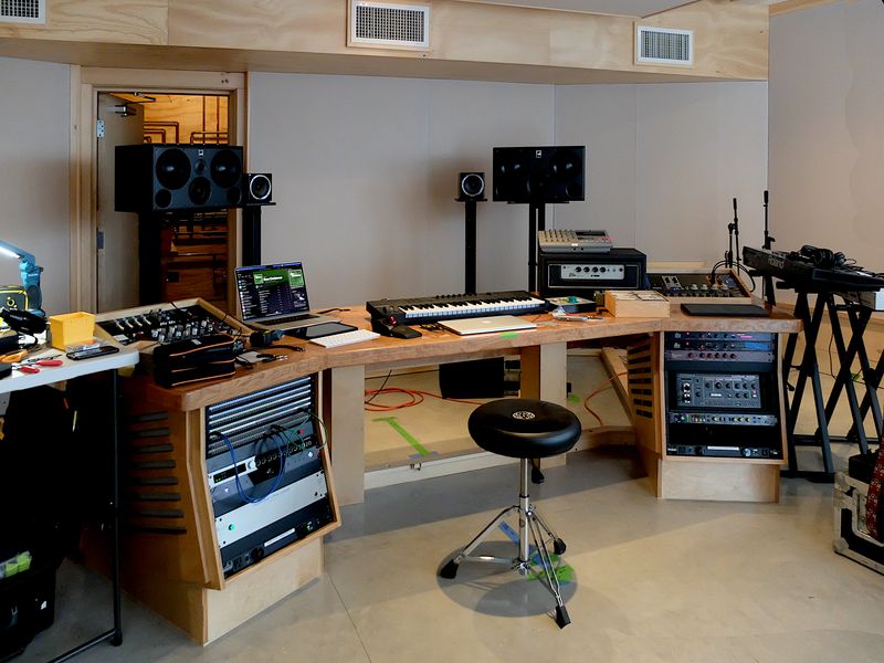
In the left rack bay you can see the patch panel. This is the brains of the wiring which brings all the cabling from the 4 mic panels and audio gear into one place where basically anything can be jumpered to anything. There was still work to be done getting software eg. ProTools updated and configured, but at this point we were basically done.

